


 1358 / 1526

PROPELLER SHAFT
5
REMOVAL FROM VEHICLE
Note :
Before removal of the driveshaft set the brakes, block
the wheels, and mark the slip yoke assembly and tube
shaft with a marking stick or paint to assure prope r
alignment when reassembled. This is known as
keeping the driveshaft yokes “in Phase”.
Unscrew bearing strap retaining bolts at pinion yoke.
Unscrew bearing strap retaining bolts of the rear shaft,
at centre bearing joint for 4x2 vehicle & 8 bolts at transfer
case end yoke (Double carder) for x4 vehicle. Disconnect
& remove rear propeller shaft. Fig. 3 / Fig. 2.
Carefully place the propeller shaft on a work table.
For 4x2, Unscrew nuts to remove centre bearing
bracket from cross member & unscrew gear box end
yoke bolts (double carder), to disconnect front
propeller shaft.
For 4x4, Unscrew bearing strap bolts at the front axle
tail pinion end yoke & transfer case end yoke and
Disconnect front propeller shaft.
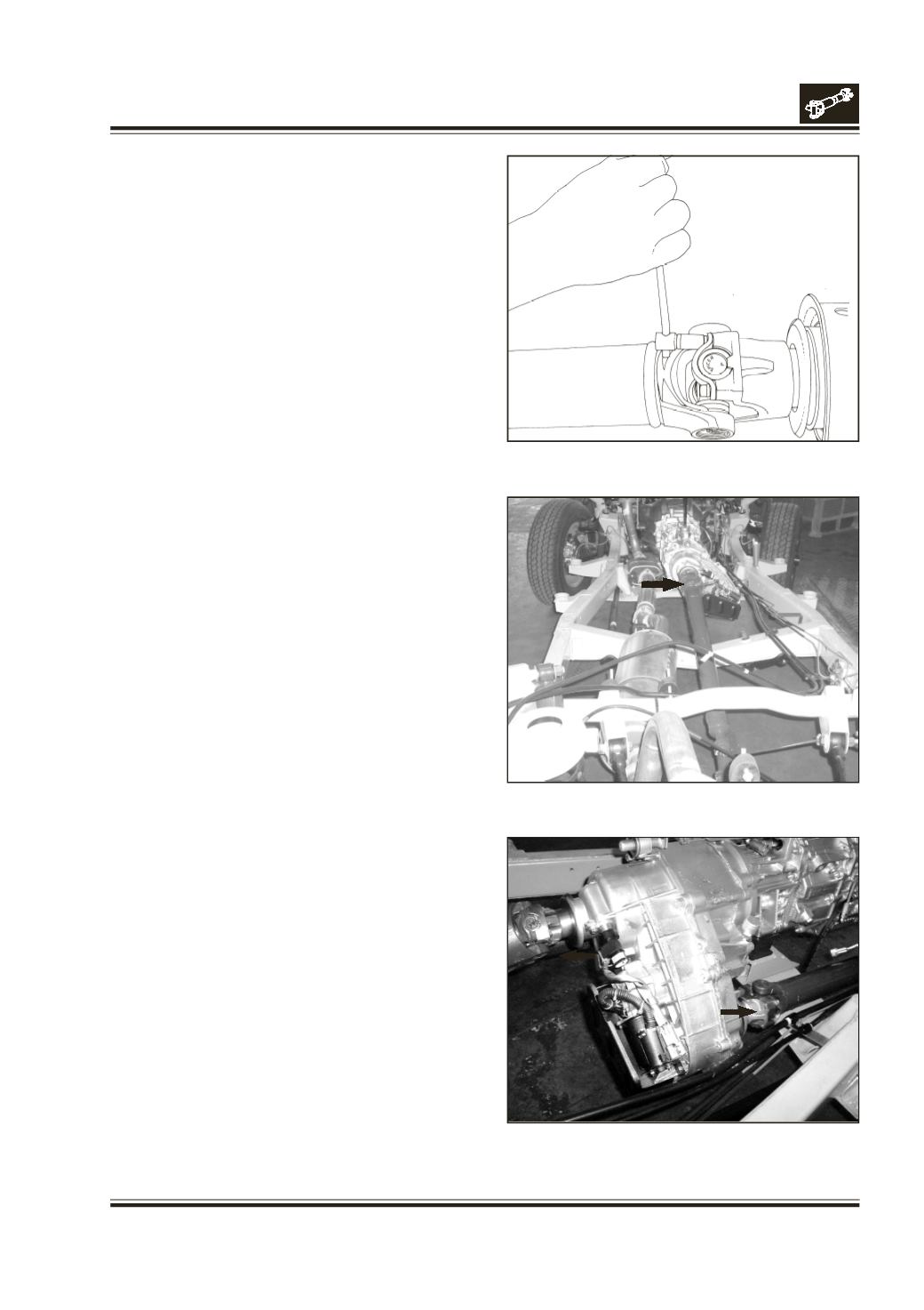
Unscrew end yoke mounting nut by holding the yoke
with holder Pt. no. 2698 5890 3505 or Pt. no. 2698 5890
4102 and using socket Pt. no. 2698 5890 4101 at gear
box or at the transfer case.
Unscrew end yoke mounting nut at tail pinion by
holding yoke with the same holder as above and using
a suitable socket. Fig. 4.
Place all parts on work table.
DISASSEMBLY
Note :
The unitized one piece seal used on Spicer driveshafts
is not intended to be removed in service. To separate
the tube shaft from the slip yoke, pull the tube out of
the slip yoke, leaving the seal in place.
A significant amount of force is required to remove as
well as reinstall the tube shaft through the seal.
Removal of the unitized seal causes damage to the
seal lip where it contacts the slip yoke.
To remove the old seal, hold the yoke assembly firmly
in a vise. Using a large chisel, drive the seal off the yoke.
FOR 4x2
Disassembly of Centre Bearing. Refer fig.1.
Mount holder Pt. no. 2698 5890 35 05 or 2698 5890
41 02 on end yoke. Grip the holder in vice. Unscrew
and remove end yoke mounting nut with socket.
Pt. no. 2698 5890 41 01.
Remove holder.
Fig. 4
Fig. 4a
Fig. 4b