


 128 / 1526

89
4 DLT ENGINE
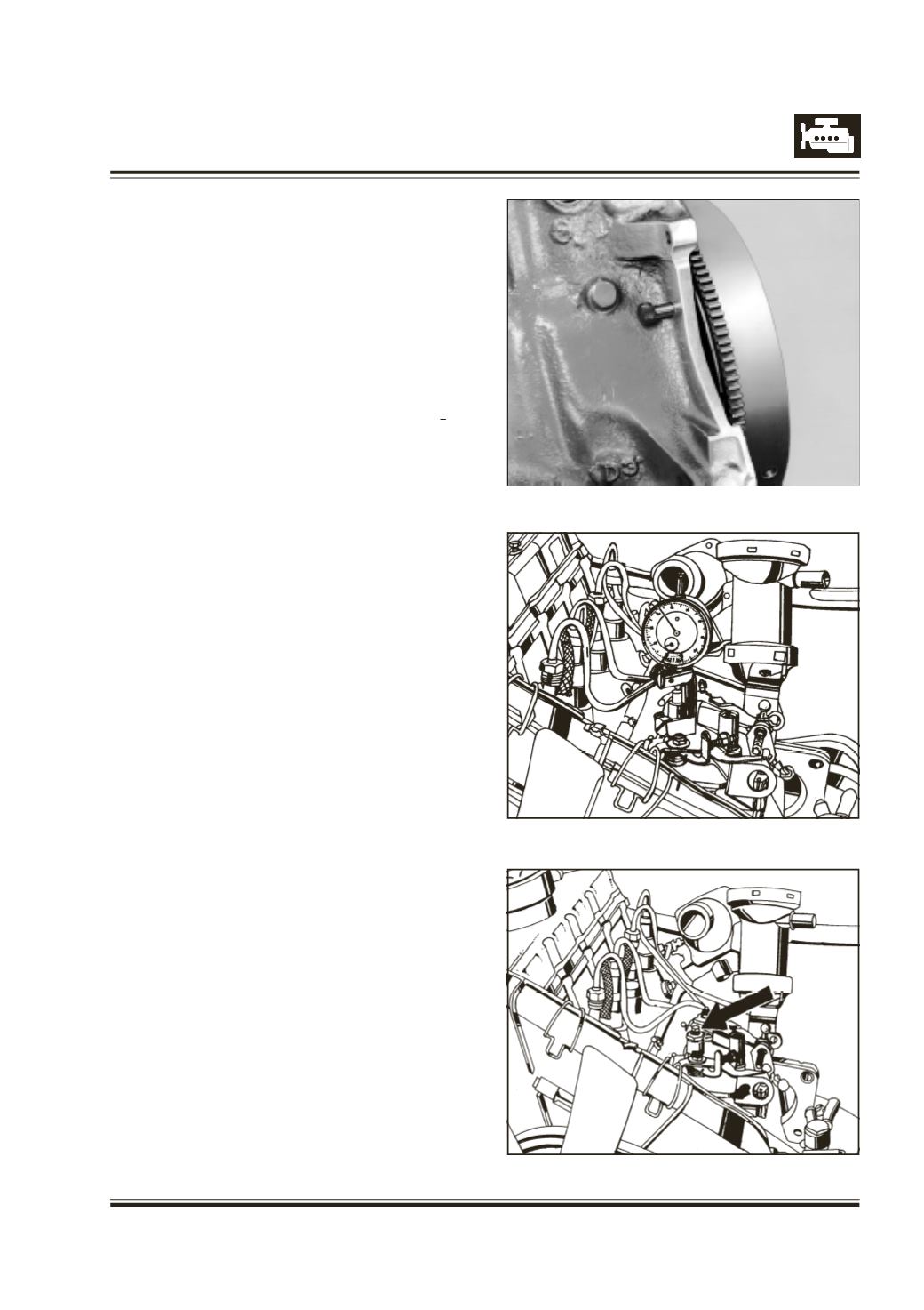
3. Remove the locking pin from the flywheel (Refer
figure 173) and rotate the crankshaft anticlockwise
(as seen from the front) by about 30 degrees till
dial gauge on FIP shows the minimum reading and
set the dial gauge to zero. Refer figure. 174.
4. Loosen the FIP mounting nuts and also the screw
for rear support for FIP.
5. Rotate the crankshaft clockwise as seen from the
front to TDC position and lock it by inserting the
locking pin in the flywheel.
6. Rock the FIP till, dial gauge on FIP reads 0.90
+0.02
mm and tighten the FIP mounting fastners.
7. Remove the locking pin and rotate the crankshaft
anticlockwise by maximum2 (two) revolutions. (DO
NOT rotate clockwise, to avoid damage to timing
spindle and dial gauge). Recheck the timing by
rotating clockwise and refitting locking pin at TDC
position. If timing is not within 0.90 ‘“ mm, repeat
the procedure (from points 3 to 6) till this is
achieved.
8. Remove the locking pin from the cylinder block,
timing bracket with dial gauge and timing spindle
from FIP. Refit the sealing plug and tighten to 0.5"
‘ mkg, and connect high pressure lines. Refer fig-
ure. 162 (DO NOT overtighten to prevent damage
to adaptor and its setting). Bleed the system be-
fore starting the engine.
NOTE: DO NOT interchange the assembly banjo
bolt fitted at fuel return line on FIP, to avoid changes
in fuel delivery values & timing advance settings.
Fig. 173
Fig. 174
Fig. 175