


 1171 / 1526

ENGINE
3
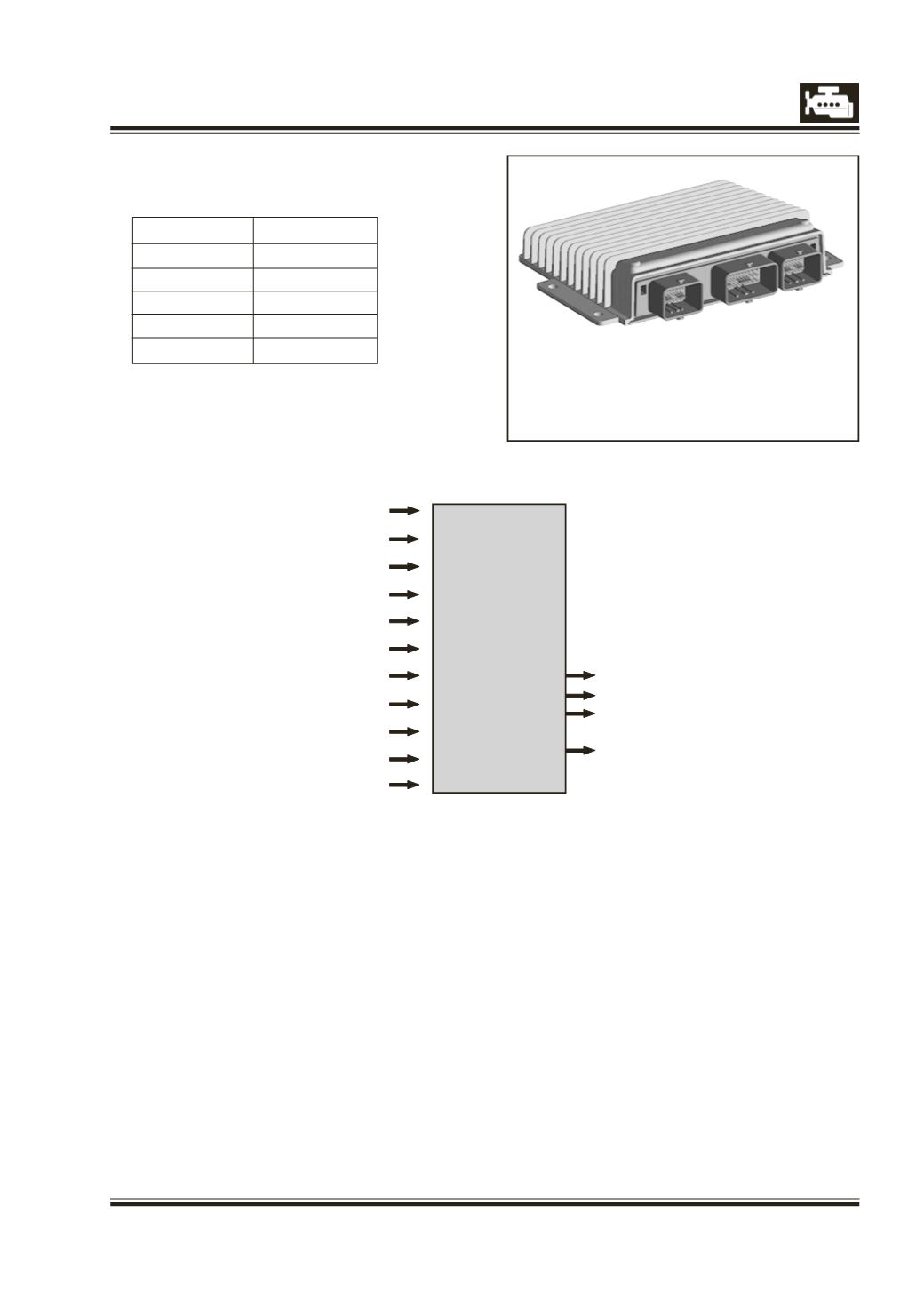
Inputs to ECU
Engine speed- crank signal
Cam signal
Pedal position
Rail pressure signal
Boost pressure signal
Boost temperature signal
Engine coolant temperature
Knock sensor signal
Fuel temperature signal
Air mass flow
Vehicle speed signal
EGR valve
Cooling fans control
Air conditioning control
Injector actuation – Delivery,
injection timing
DCM 3.1
ECU
Outputs to ECU
Data line
32bit Black
Clock
40
Flash
448
RAM
26
EEPROM
2
SOP
2002
ELECTRONIC CONTROL UNIT & SENSORS
ELECTRONIC CONTROL UNIT (ECU)
Software Strategies
l
Fuelling control including Idle
l
Timing control
l
Max speed control and flyup
l
Driveability
l
Fault detection
l
AC control
l
Engine cooling fans control
l
Corrections for different environmental
conditions- hot climate, cold climate, altitude
ECU:
The Electronic control Unit is a 32 bit
microprocessor which controls the injection
parameters as well as some of the vehicle related
outputs. The ECU receives input from various
sensors located on the engine and the vehicle to
decide the injected quantity and injection timing
best suited for the engine to work with maximum
efficiency and safety. Input to the ECU is received
from Crank sensor, Cam sensor, Vehicle speed
sensor, Pedal sensor, Rail Pressure Sensor, Fuel
Temperature sensor, Coolant temperature senor, Air
mass flow sensor, Boost Pressure and Temperature
sensor, atmospheric pressure sensor, Knock sensor
and water-in-fuel sensor. Based on all these inputs,
the ECU controls the injectors directly for the
required injection quantity and injection timing. It