


 1100 / 1526

60
GEAR BOX G-76
28. Improvements –Supplement
Note: Please refer this supplement in conjunction
with the assembly/dismantling procedure
explained in G-76 Gear Box group in this manual.
Basic overhauling procedure remains same as
explained for G-76 (4 gate) Gear Box.
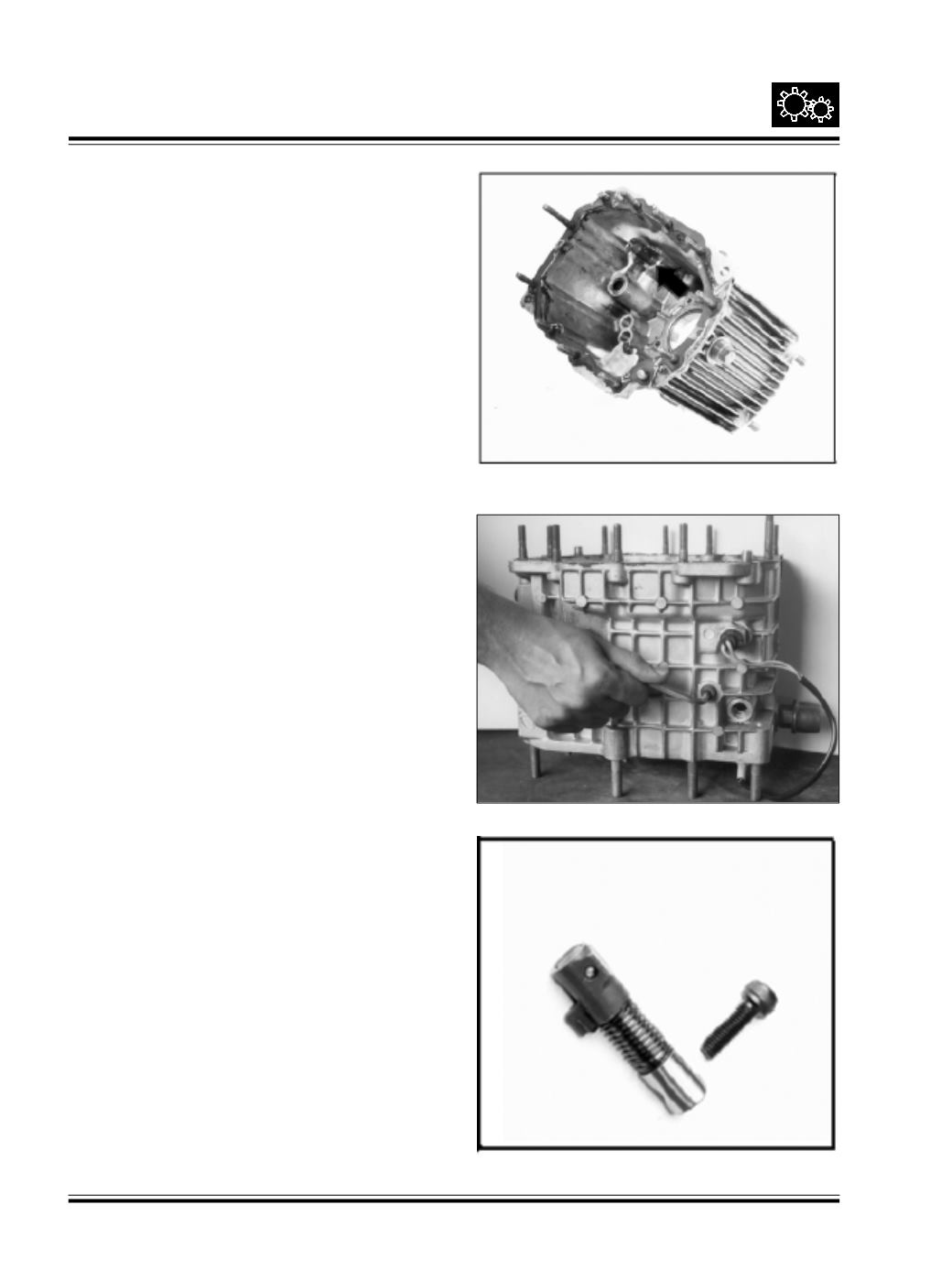
Procedure to remove inhibitor assembly:
The inhibitor is located in housing front half.
Ref Fig. 132
Fig. 132
Fig. 134
Fig. 133
Loosen allen screw & take out inhibitor assy.
Ref Fig. 133 & 133