


 417 / 1018

DRIVETRAIN-TA65 Star
26
4
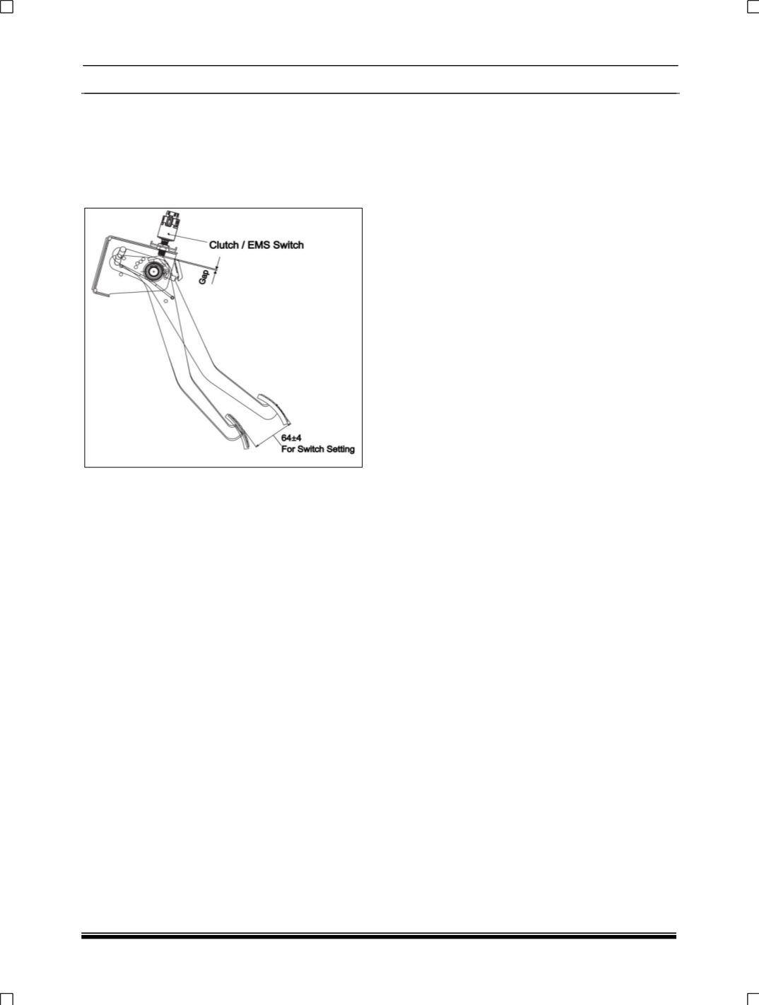
.6. E CLUTCH SWITCH ADJUSTMENT
PROCEDURE:
EMS switch gap as shown in the below image
should be set such that the switch becomes
'ON' at 64±4 mm of clutch pedal travel from its
initial position.
To ensure clutch pedal height setting properly,
follow below instructions.
After setting clutch pedal in line with brake pedal,
pump the clutch pedal for 10 to 15 times, after that
start engine and run the vehicle for 2 to 3 Kms with
clutch pedal actuations like city cycles traffic
bumper to bumper, check clutch pedal height and
reset if required.
4.6. F. REMOVAL OF CLUTCH FROM THE CAR:
1. Position and Lift the car using two post lift.
2. Disconnect battery and electrical connections of
the starter motor.
3. Loosen mounting bolts and remove starter
motor. Disconnect and remove transaxle along
with clutch housing from engine (for procedure
refer transaxle group)
4. Remove clutch release bearing with sleeve
5. Support clutch pressure plate and clutch disc
with mandrel & remove.
NOTE:
1.
It is recommended to replace a defective disc
having any of the above mentioned defects with
a new genuine clutch disc. We do not
recommend removal and replacing of clutch
facing.
2.
We do not recommend overhauling of the
clutch pressure plate assembly. However,
before re-fitment, the assembly should be
checked for specifications and should conform
to the data of clutch pressure plate assembly
given on page 3.
3.
Use correct clutch discs for the 1.22 NG NA
versions Identification.
4.
Use Disc and Pressure plate of the same make.
Ensure that the clutch facing material is not
contaminated with oil or grease as this shall
result in clutch slipping.
4.6. G. INSTALLATION OF CLUTCH ON THE
CAR:
Carryout the clutch removal steps in appropriate
sequence for its fitment. However, following care
must be taken during installation.
Clean friction face of flywheel and check for
cracks, scoring, burn marks or unevenness. If
necessary, machine flywheel friction face just to
clear the defect.
Lightly apply Dow corning P40 grease on the disc
splines. Install disc and pressure plate assembly.
Press the aligning mandrel through the pressure
plate assembly and clutch disc and centralize
clutch disc on flywheel by locating the mandrel at
the flywheel end.
NOTE:
Do not mix clutch mounting bolts with other
fasteners. Do not use longer or shorter screws.
Longer screws may not tighten the clutch at all.
Shorter screws will not provide enough threads to
achieve desired tightening.
While tightening the clutch mounting screws
check aligning mandrel for continuous free
sliding to ensure concentric installation of clutch
disc which will avoid trouble during the
installation of the transaxle.