


 494 / 1525

19
BRAKES
Note :
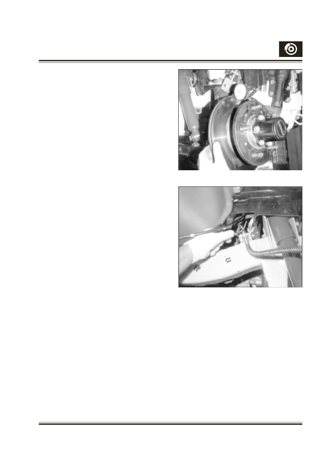
Measure the face runout of the disc (Fig. 13) & mark
the low runout point around the wheel mounting bolt,
nearest to the low run out point. This is important, as
this marked point has to be matched with
corresponding high runout point on the hub. This will
ensure minimum runout of hub and disc assembly
together & will intern minimise disc wobbling & uneven
pad wear.
Fit the bottom guide pin dust cover’s other end to
carrier. Fit new pads as explained under “Fitment of
New Pads”. Swing back the caliper to its place and fit
guide pin retaining bolt and tighten to recommended
torque 3.1 to 3.5 mkg.
Fit bleed screw and tighten to a torque of 0.55 to 0.8
mkg. Connect banjo end of the hose with caliper body
by fitting banjo bolt using new gasket. Before fully
tightening the banjo bolt, make sure that the other
end of the hose is anchored to the chassis end. In
this condition the hose should be free from twists.
Tighten the banjo bolt to a torque of 3 to 4 mkg.
Connect pipe nuts to the female end of the hose after
removing the dust cap from the bundy tube and tighten.
Caliper carrier mounting bolts to be checked for its
tightness to a torque of 6.3 to 8.3 mkg.
The other side of the caliper can be serviced in the
same way.
Bleed the brake system.
If bleeding equipment or power bleeding is used to
bleed the system, which does not necessitate
application of pedal, youmust make sure several brake
pedal applications are made to maintain minimum
clearance between pad and the disc before taking the
vehicle for road test.
HOSE REPLACEMENT (
Fig. 14)
Hoses to be replaced as per recommended service
schedule.
Use light and mirror to inspect hose condition, check
brake hoses and pipelines for leakage, crack and
damage etc. & replace if necessary.
Fig. 13
Fig. 14