


 1506 / 1525

18
BODY
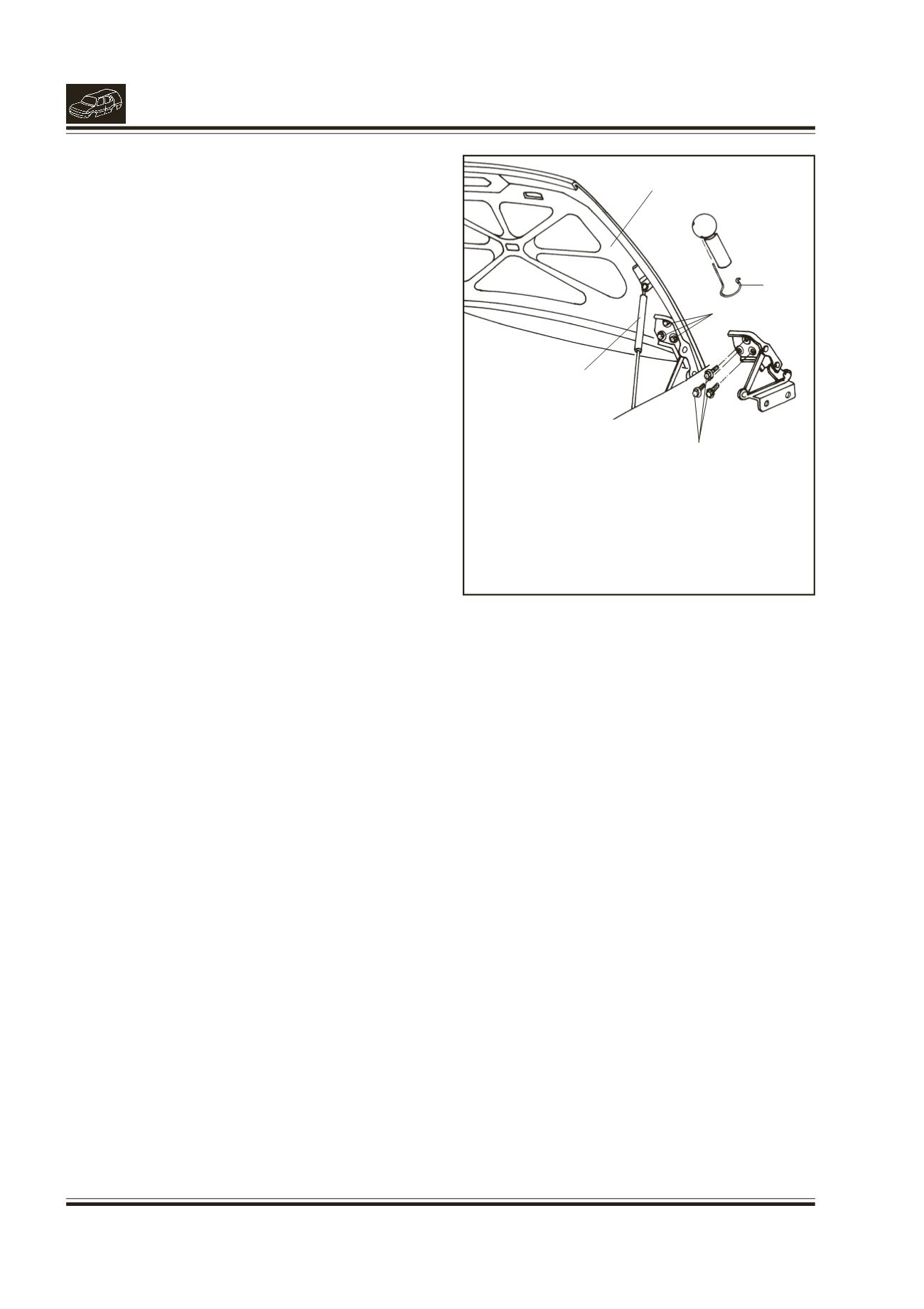
13. REMOVAL/INSTALLATION OF BONNET
(Fig. 18)
REMOVAL
l
Open the bonnet and support it with a suitable
method.
l
Disconnect engine inspection lamp.
l
Remove ball joint locking clips of balancer rod and
remove balancer rod from RH & LH sides.
l
Support the bonnet properly and remove hinge
mounting screws on bonnet from RH & LH sides.
l
Remove the bonnet.
INSTALLATION
l
Locate the bonnet on the hinges
l
Support the Bonnet with a suitable method and
hold it in proper position.
l
Fit 3 flanged screws for hinge mounting RH & 3
flanged screws for hinge mounting LH to the
bonnet.
l
Ensure correct position of the bonnet by closing
and opening the bonnet.
l
Assemble balancer rod on ball pins and lock with
locking clips on RH and LH side.
l
Tighten the hinge mounting screws.
l
Connect the engine inspection lamp.
Fig. 18.
1.
LOCKING CLIP
2.
BALANCER ROD
3.
MOUNTING SCREWS
4.
BONNET
1
2
3
3
4