


 1293 / 1525

ENGINE
126
Fig. 8
Fig. 9
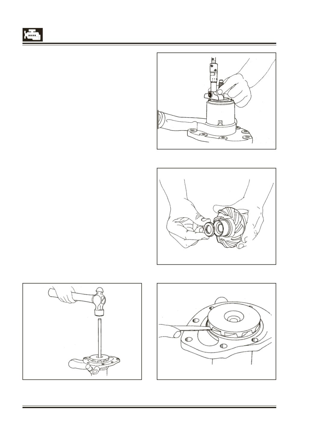
Fig. 10
Fig. 7
5 Place the water pump housing on the fixture.
6 Place the water pump shaft in the housing with
the threaded end up.
7 Apply grease on inner bearing and press it down
with the help of mild steel tube 150 mm long, 25
mm OD and 16.5 ID. mm length of tube on one
end should be turned to reduce OD to 23 mm.
8 With the same tool press down the spacer tube.
The hardened surface of the spacer tube having
the larger chamfer should be on the top. Spacer
has an interference fit on shaft and should be
heated in oil before pressing.
9 Apply grease on outer bearing inner race and
press down with the help of this tube.
10 Fit outer race of outer bearing with special tool,
Part No 312 589 03 39 or 2574 5890 99 04. Fig. 7.
11 Measure projection of outer bearing outer race
top surface from water pump housing. Fig. 8. Then
select shims of thickness 0.02-0.07 mm more than
the projection measured. Apply graphite oil on the
shaft surface mating with the outer seal. Fit seal
in plate and fix plate with four screws, placing the
selected shims with gasket between housing and
plate. Tighten screws to specified torque and then
lock them.
12 Fit new insert and rubber sleeve into the impeller.
Fig. 9.
13 Invert water pump housing and press down
impeller till a gap of 1 mm is maintained between
the impeller vanes and housing. Ensure the gap
with feeler gauge. Fig. 10. Impeller to be heated
in oil before pressing.