


 1283 / 1525

ENGINE
116
Fig. 1
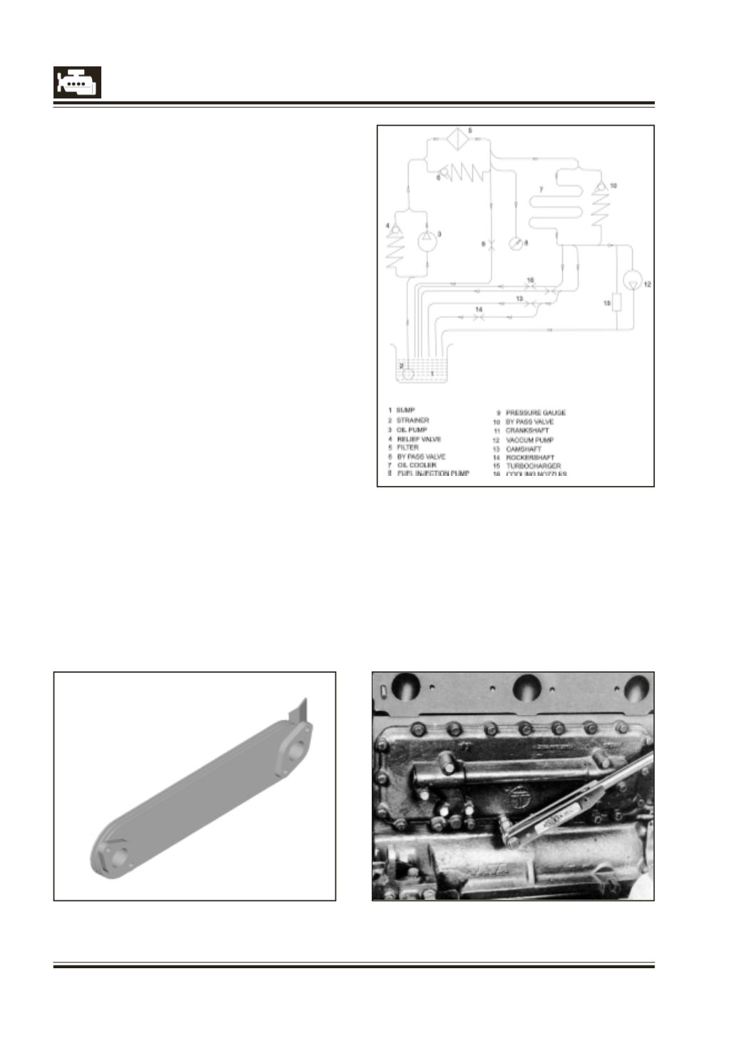
Circuit diagram
Fig. 1a
Fig. 1b
ENGINE LUBRICATION SYSTEM
Fig 1
OIL COOLER
3 plate oil cooler with heat rejection rate
- 10000 Kcal/Hr.(fig 1a).
Piston cooling nozzles fitted in cylinder block to
keep the piston temperatures under control for
high bmep/pfp (high thermal loads).
REMOVAL OF OIL COOLER
1 Drain cooling water from radiator and crankcase.
2 Disconnect exhaust pipe from manifold Loosen
exhaust manifold mounting bolts and remove
exhaust manifold.
3 Remove starter motor and alternator.
4 Unscrew screws holding oil cooler cover to
crankcase and remove oil cooler with cover. Do
not loosen the 4 screws at the centre of the oil
cooler as they only keep oil cooler cover and oil
cooler together. Fig. 1b. Remove remaining 4
screws and separate oil cooler from cover.
PRESSURE TESTING OF OIL COOLER
1 Assemble oil cooler and its cover with the gasket
between them. Screw on and tighten screws to
specified torque.s
2 Fix sealing plate on cover opening.
3 Connect rubber hose to hand operated water
pump dipped in hot water container (water
temperature 70 to 80 deg C).
4 Pressure test oil cooler at a pressure of approx. 5
bar and check for leakages, if any.
5 Replace leaky oil cooler/cover.
6 Dismantle the assembly. Clean oil passages in
cover with kerosene and blow dry with
compressed air.