


 1256 / 1525

ENGINE
89
Fig. 9
Fig. 10
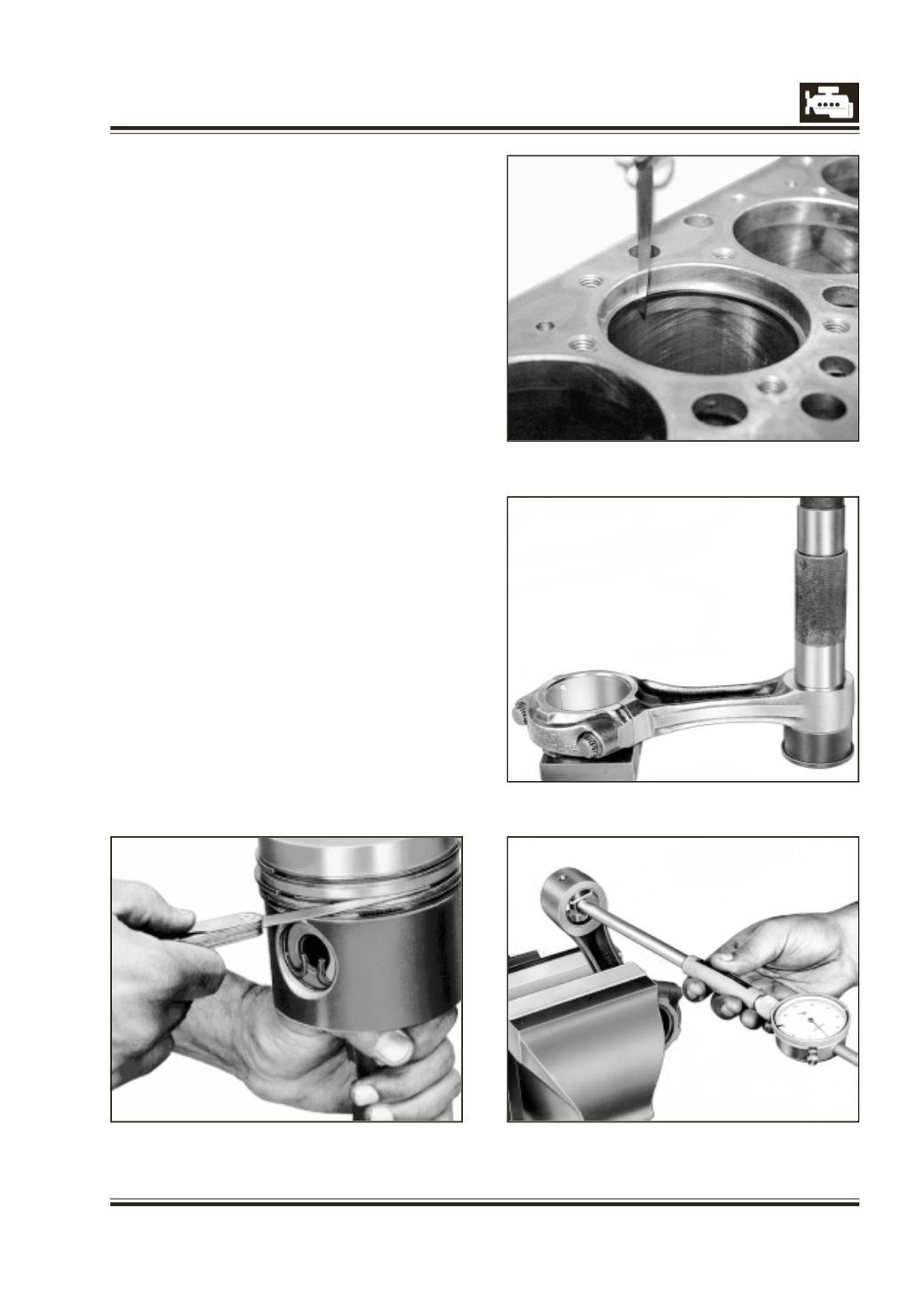
Fig. 11
Fig. 12
4 When cylinders are honed or bored and honed,
piston and rings of appropriate size should be
used. Piston size is stamped on the piston crown.
Specified piston clearance in cylinder bore should
be maintained.
5 Install piston rings using piston ring expander Fig.
8 starting from third groove. ‘TOP’ mark on 2nd
ring should face piston crown.
INSPECTION AND REPAIR OF CONNECTING ROD
1 Inspect small end bush of connecting rod and if
necessary remove bush with drift, 2576 5890 02
07. Fig. 11.
2 Check connecting rod small end parent bore wear
with internal measuring instrument Fig. 12.
3 If necessary, machine it to next repair size on a
suitable boring machine. Ensure that connecting
rod big end and small end axis are parallel within
specified limits.
4 Install new bush using drift, 2576 5890 02 07. Oil
parent bore in connecting rod before pressing
bush. Fig. 13.
5 Finish connecting rod small end bush bore on a
connecting rod boring machine. Alternatively bush
may be reamed.
6 Assemble connecting rod cap without bearing
shells and tighten fastening bolts with a torque
wrench to specified torque.
NOTE
: Ensure that identification numbers for
connecting rod and cap are matched and notches
for bearing shells are on same side.