


 1253 / 1525

ENGINE
86
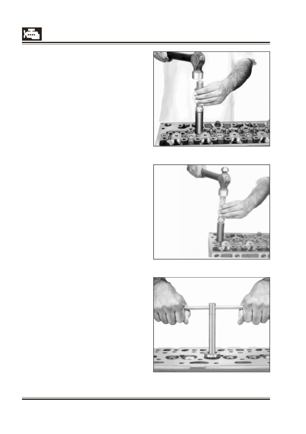
Fig. 11
Fig. 12
Fig. 13
INSPECTION OF VALVE
1 Check-valve head thickness. If the valve head
thickness is less than specified value, replace
valve.
2 Check valve stem for wear and scores. Replace
valve having excessive scoring and wear on stem.
3 Check valve seat and valve stem for concentricity.
If runout exceeds specified limits, replace valve.
4 If contact pattern of valve is not around entire
seat, valve seat may be defective and machining
of valve seat is imperative.
5 After machining valve/valve seat cylinder head
parting surface, it is necessary to check length of
spring in installed condition (valve fully closed).
Spring length in installed conditionmust be within
specifications.
REMOVAL AND INSTALLATION OF VALVE GUIDES
1 Place cylinder head on suitablewooden supports.
2 Force guide out of cylinder head with drift, 2651
5890 05 01 for inlet valve guides and 2651 5890 05
02 for exhaust valve guides. Fig. 10.
3 Check parent bores for guides in cylinder head and if
necessary ream bore to next repair size.
4 Coat new valve guide and its bore in the cylinder
headwithgraphiteoil. Positionvalveguide incylinder
head bore with taper on the out side diameter at
bottom. Circular grooves arecut onout sidediameter
of exhaust valve guides for identification.
5 Slide spacer, 2651 5890 05 03 over valve guide.
6 Install inlet valve guide with drift, 2651 5890 05 01
and exhaust valve guidewith drift,
2651 5890 05 02. Fig. 11 & 12.
NOTE
It is advisable to use suitable press for removal and
installing valve guides in cylinder head.
7 Above drift with spacer ensures the dimension
between valve spring seat and valve guide tip.
However, it should be ascertained by physical
checking.
8 Ream inside diameter of inlet valve guides with
reamer 636 589 02 53 and exhaust valve guide
with reamer 2576 5890 02 02. Fig 13 & 14.