


 333 / 1588

31
TRANSFER CASE
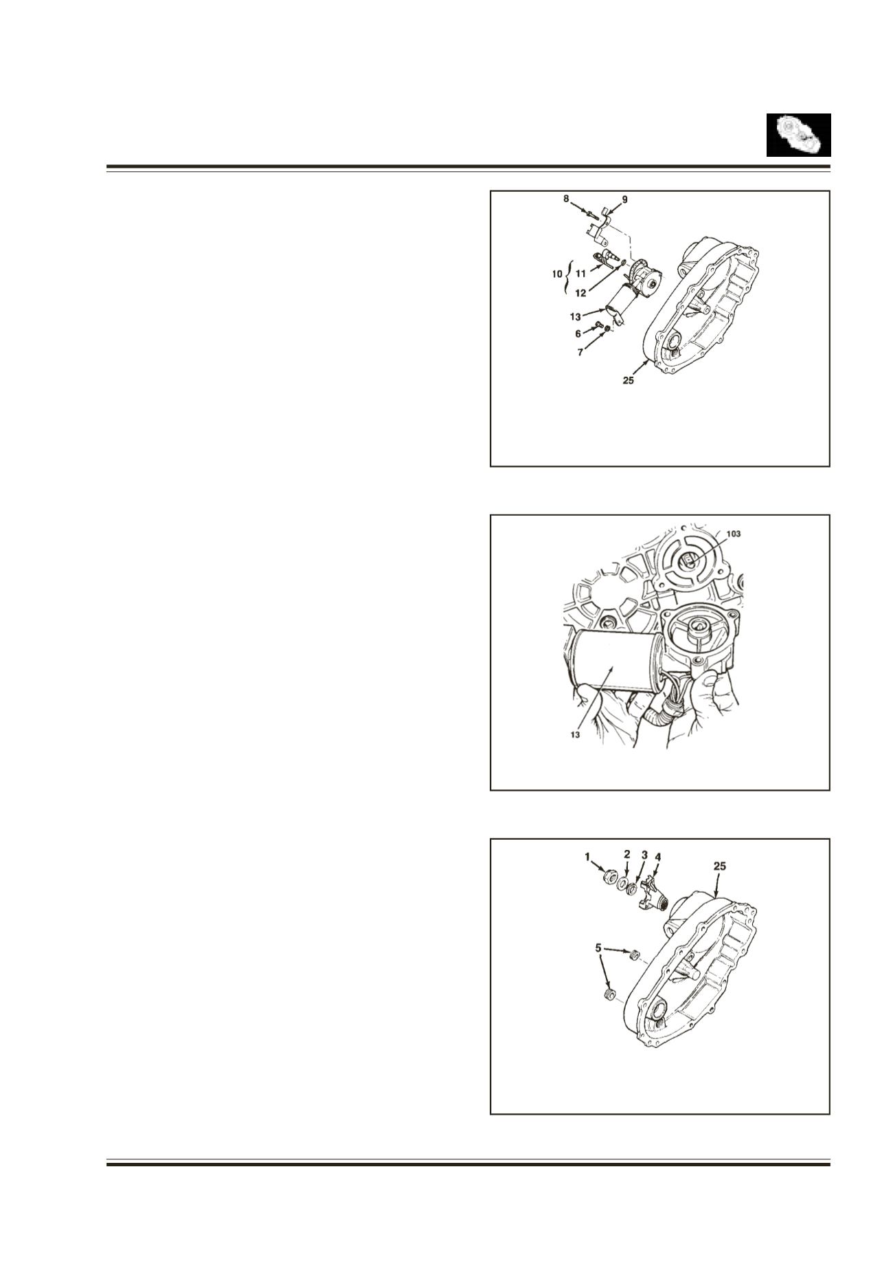
External Electric Shift
Refer fig. 38&39
Align the motor with shift shaft and position the motor
assembly onto the cover.
Install the motor to the shift shaft and contact cover.
Rotate the motor clockwise direction to check correct
engagement.
Insert the O-ring on the speed sensor and install the
speed sensor assembly to the cover.
6.
BOLT
7.
WASHER
8.
BOLT
9.
SENSOR & HARNESS
BRACKET
10.
SENSOR ASSY.
11.
SPEED SENSOR
12.
O-RING
13.
MOTOR ASSY.
25.
COVER
13.
MOTOR ASSY.
103.
SHIFT SHAFT
1.
NUT
2.
WASHER
3.
SEAL
4.
REAR YOKE
5.
PLUG
25.
COVER
EndYoke
Fig. 40
Install the two plugs to the cover.
Install the end yoke, seal and washer.
Holding the end yoke tighten the nut.
Note
: Apply Loctite 262 to nut before installation
Fig. 38
Fig. 39
Fig. 40
Install the bracket to the motor assembly and tighten
three bolts.