


 331 / 1588

29
TRANSFER CASE
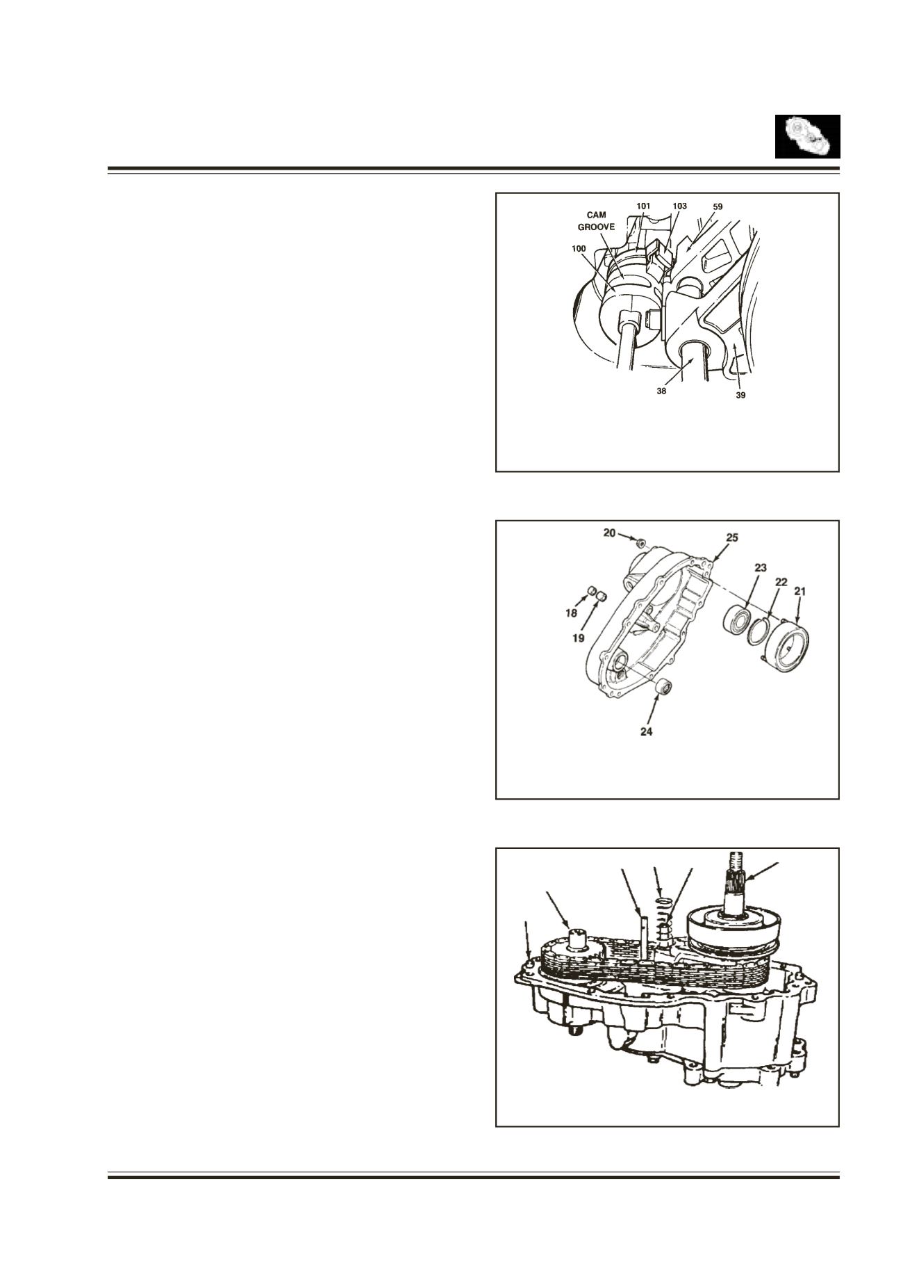
Install the previously assembled electric shaft cam
and assemble the clutch housing as follows:
Refer
fig. 33
Rotate the shift cam assembly to right so that
the end of the torsion spring contacts with
reduction shift fork inside.
Holding the rail shaft, lift up the fork assembly
slightly. Adjust electric shift cam assembly so that
the roller on reduction shift cam assembly is in
groove in shift cam and button on lockup fork is
on cam end.
Install the clutch housing assembly.
Cover
Fig. 34
Position the cover with the open end facing up on the
table.
Position the end of needle bearingwith the identification
mark up and press into the cover until upper end of
bearing is 40.47 - 40.97 mm below cover face that
contacts with transfer case.
Press the ball bearing into cover and install the snap
ring. Install remaining parts as follows
* Install the four O-rings on the stud bolts of the
clutch coil assembly.
* Install the clutch coil assembly inside the cover
and tighten three nuts.
* Install the bearing and motor bearing into the
cover.
Cover Assembly
Fig. 35
Install the return spring over rail shaft in the transfer
case
Insert the magnet into the transfer case slot
Apply about 1.6 mm bead of Loctite RTV598 to the
transfer case mounting surface. For installation of
cover, align the transfer case with cover. Do not use
excessive force.
38. RAIL SHAFT
39. LOCKUP FORK
59. REDUCTION SHIFT FORK ASSY
100. ELECTRIC SHIFT CAM
101. TORSION SPRING
103. SHIFT SHAFT
18.
OIL SEAL
19.
BEARING
20.
NUT
21.
CLUTCH COIL ASSY
22.
SNAP RING
23.
BALL BEARING
24.
NEEDLE BEARING
25.
CASE COVER
29.
RETURN SPRING
38.
RAIL SHAFT
55.
OUTPUT SHAFT
71.
FRONT OUTPUT SHAFT
103.
SHIFT SHAFT
109.
DOWEL PIN
109
71
103 29 38
55
Fig. 33
Fig. 34
Fig. 35