


 143 / 1588

104
4 DLT ENGINE
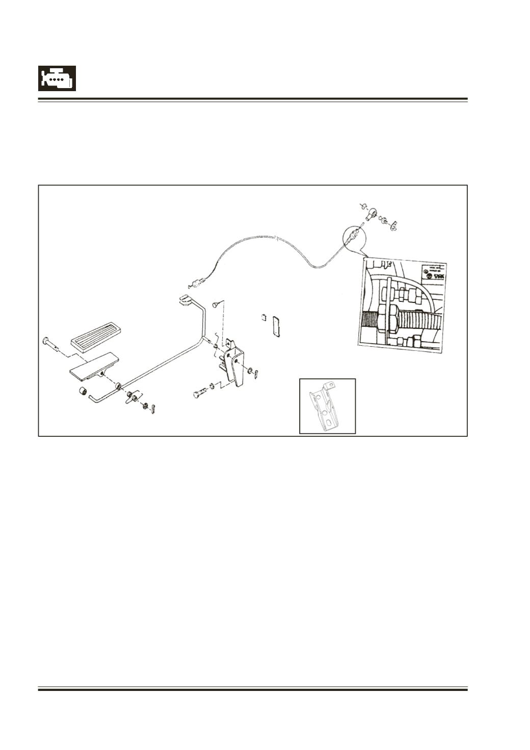
Fig. 193 Accelerator Exploded View
Description
1 Accelerator Cable LHD
1 Accelerator cable RHD (Acey)
2 Accelerator rod LHD
2 Accelerator rod
3 Bracket (acc. Pedal Mtg.)
4 Rubber Stopper
5 Spring (for ACC Rod)
6 Spacer
7 Split Pin 3.2 x 16
8 Pedal Plate
9 Spring (accelerator Pedal Return) LHD
ACCELERATOR CABLE
Introduction
The FIP which is mounted on the engine is operated
through a accelerator cable which connects one end
to accelerator pedal and other end to FIP. The
9 Spring
10 Rubber Cover
11 Ball Pin
12 TabWasher
13 Ball End B10
14 Locking Ring 10
15 Bracket (acc. Pedal Mtg.) LHD
17 Rubber Sleeve (for Accelerator Rod.)
18 Clevis Pin (accelerator Control)
19 Split Pin 1.6 x 10
20 Packing Foam
21 Packing Foam
accelerator pedal travel, controls FIP throttle lever
through cable which controls the speed of the vehicle.
18
10
8
17
9
19
2
3
5
4
6
20
7
21
14
13
11
12
15