


 1314 / 1588

ENGINE
115
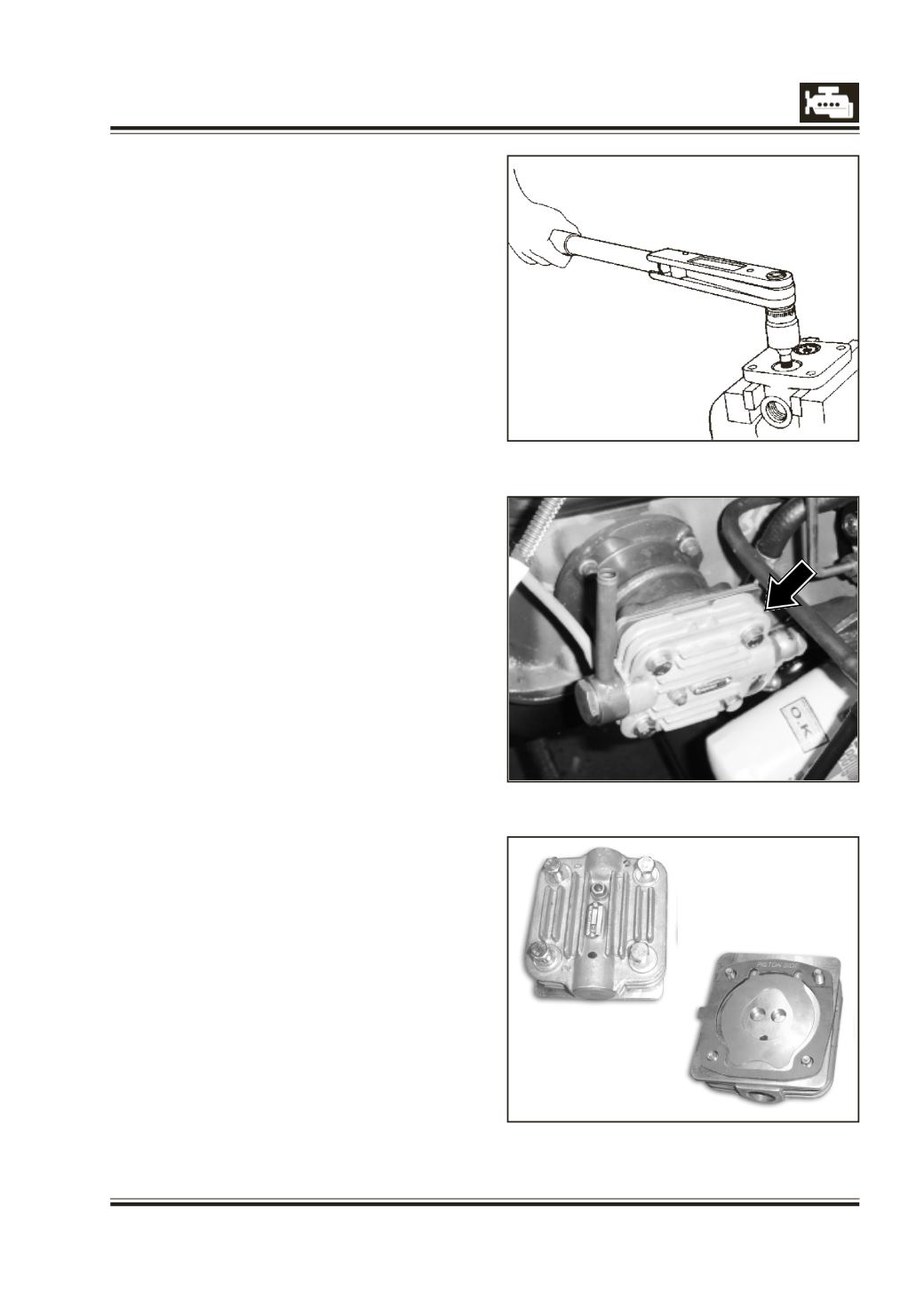
Fig. 12
Vacuum Pump cylinder head (New)
Vacuum pump suction unit (New) 77 mm dia.
9 Insert suction valve components into cylinder
head and screw on suction valve cap with adapter,
321 589 02 07 and tighten to specified torque.
Fig. 11.
10 Insert delivery valve components into cylinder
head and screw on delivery valve seat with
adapter, 312 589 09 07 Fig. 12 and tighten to
specified torque.
NOTE :
Although valve discs and springs of the suction
and delivery valves are identical, these parts
should be assembled in correct sequence as
shown in Fig. 6 as they are functionally different.
Suction port in the head is marked ‘S’. Fit suction
valve seat with ground surface on top. Centralise
valve disc on seat. Place spring on disc and screw
in suction valve cap carefully. If in this process disc
and screw in suction valve cap carefully. If in this
process disc has shifted, cap cannot be screwed
home fully. In such a case, dismantle and carefully
assemble the parts again.
Delivery port in the head is marked ‘D’. Assemble
delivery valve in proper sequence viz. spring
housing, spring, valve disc and valve seat. Valve
seat ground surface should face valve disc.
11 Install cylinder head on cylinder sleeve using new
gasket and tighten mounting bolts to specified
torque.
12 Crank engine 2 to 3 times and ensure that
compressor piston does not touch cylinder head.
13 Install air inlet and outlet connections. To avoid
wrong connections the inlet side of the head is
provided with M22 thread and outlet side with
M20 thread.