


 1209 / 1588

ENGINE
10
Dirt entry into the systemmust be totally prevented
as CR system uses extremely close tolerance parts
Checking faults:
l
Connect diagnostic tool to diagnostic socket of
wiring harness(16 pin)
l
Select the correct application
l
Every fault has unique Fault code
l
Diagnostic tool gives fault codewith faultdescription
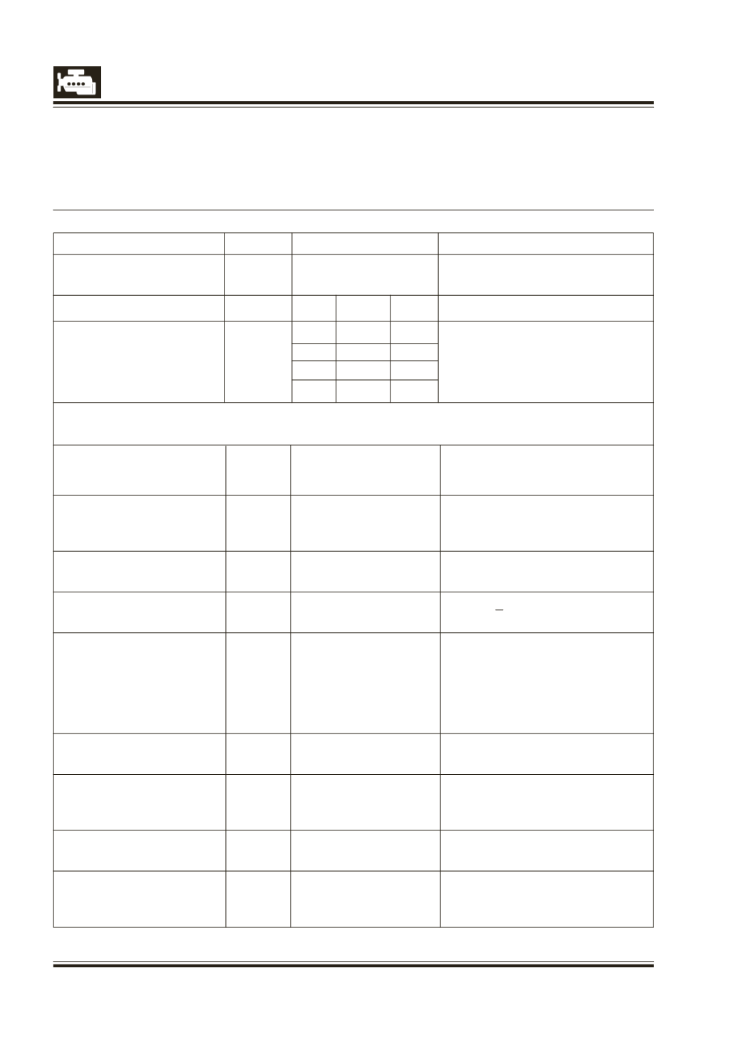
SENSOR CHECK VALUES :
Components
Sensors
DCU
Resistance Valuus
IMV
Non
87 (OCR control)
5.3 /-10%
polarised
HSD LSD Cyl
117
114
1
Injectors
Non
118
121
3
180 m
polarised 117
115
4
118
120
2
Warning : It is impossible to measure resistance below 1 with a traditional multimeter. Use the
KELVIN method (with 4 wires) to measure the injector resistance
Pin A 25 (measurement)
Integrated circuit (non measurable
Rail pressure sensor
Pin B
26 (earth)
resistance
Pin C 6 (+5V supply)
Pin 1
99(measurement)
Integrated circuit (non measurable
TMAPsensor
Pin 2
108 (+5V supply)
resistance
Pin 3
100(earth)
Diesel temperature
Pin 1
109 (measurement)
Function of temperature
sensor
Pin 2
110 (earth)
Engine speed
Pin 1
90 (+ single)
1090 + 15%
sensor
Pin 2
82 (- single)
Pin 1
51 (2.5 V supply track 2)
1.25 k +/ -20% between sensor
Pin 2
72 (2.5 V supply track 1)
terminals 1 and 5
Pedal sensor
Pin 3
53 (earth track 1)
0.9 k + / -20% between sensor
Pin 4
71 (Signal track 1)
terminals 2 and 4
Pin 5
70(earth track 2)
Pin 6
32 (Signal track 2)
Accelerometer 1
Pin 1
45 (+ single)
Piezoelectric sensor
Pin 2
46 (- single)
Pin 1
111 (+5V supply)
Cam sensor
Pin 2
103 (measurement)
Half effect sensor
Pin 3
104(earth)
Coolant temperature
Pin 1
101 (measurement)
Function of temperature
sensor
Pin 2
102 (earth)
Pin 1
36 (measurement)
Vehicle speed sensor
Pin 2
Not connected to DCU
Half effect sensor
Pin 3
Not connected to DCU