


 1207 / 1588

ENGINE
8
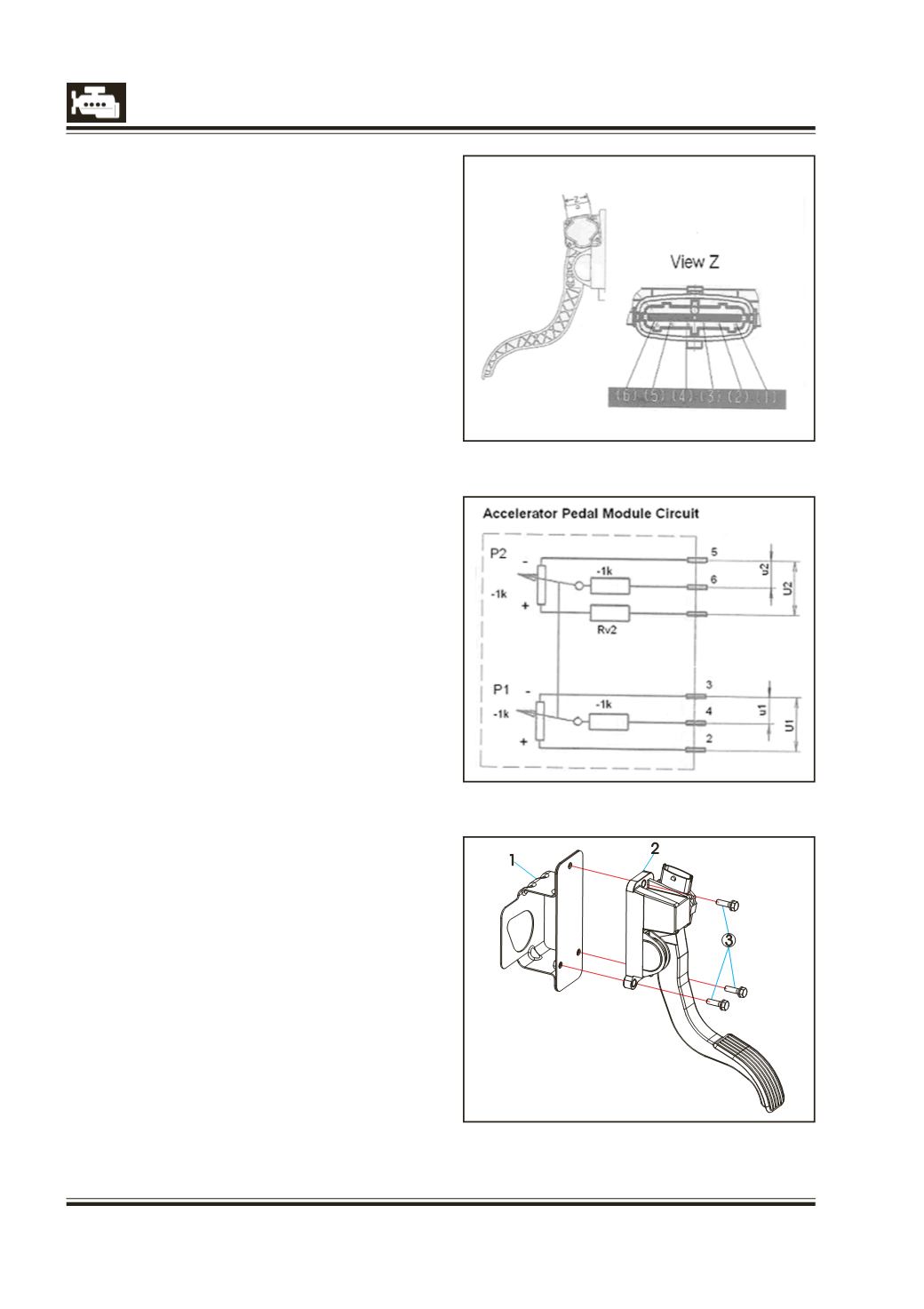
15. Accelerator Pedal
Accelerator pedal Module
The Sensor serves to measure the position of the
accelerator pedal. It has two potentiometer for
measuring the position of accelerator pedal from
0% travel position to 100% travel position. The
accelerator pedal module is part of accelerator
pedal as shown in the figure. Tightening torque of
the retaining screws : 9 Nm.
Specifications:
Operating voltage : 5 ± 0.3 DC
Short-circuit protection : 60 min. at 16 V
Double-potentiometer
Potentiometer 1 : 1.2 k
Ω
± 0.4 k
Ω
Potentiometer 2 : 1.7 k
Ω
± 0.8 k
Ω
Checking Procedure :
The resistance values can be checked with help of
a multimeter as per the circuit diagram shown
above. The Accelerator pedal module is not
repairable. The checking procedure is to ascertain
whether the Accelerator pedal module is defective
or not. If defective, the accelerator pedal with
module has to be replaced as an assembly.
1
Accelerator Pedal Layout
1. Assy. Bracket
2. Accelerator Pedal
3. Hex. Flange Screw
Precaution
Sensor connections should not be removed
unnecessarily