


 73 / 1235

ENGINE
41
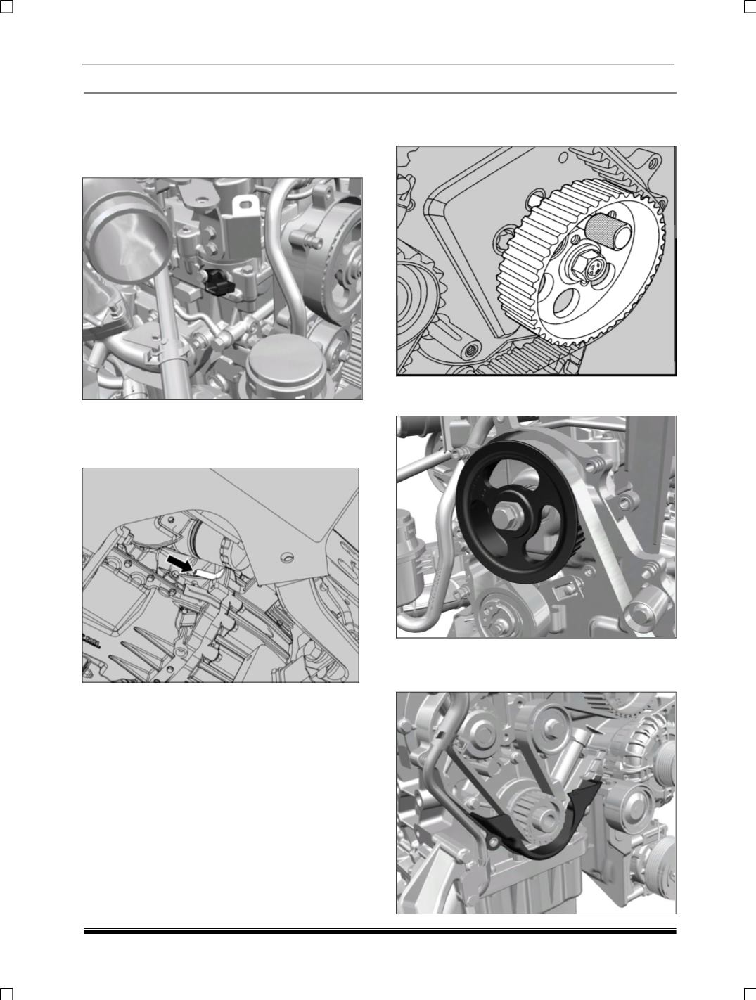
4. Disconnect electrical connection from cam phase
sensor.
5. Remove the cam phase sensor and insert the
locking pin (Part no. 2653 5890 06 09) for on ve-
hicle ease for locking the camshaft.
6. Lift the vehicle and remove the stone guard.
7. Lock the flywheel using locking pin
(Part no. 2870
5890 06 01) to bring the piston of No.1 cylinder to
TDC position.
8. Align hole on the HP mounting bracket and lock
the gear with the help of locking pin
(Part no.
2653 5890 06 07).
9. Loosen the camshaft gear and remove the cam-
shaft gear flange.
10.Release the timing belt tension by loosening the
auto tensioner mounting bolt.
11.Remove the timing cover lower.