


 534 / 1235

FRONT AXLE (4X4)
35
FRONT AXLE
(4X4)
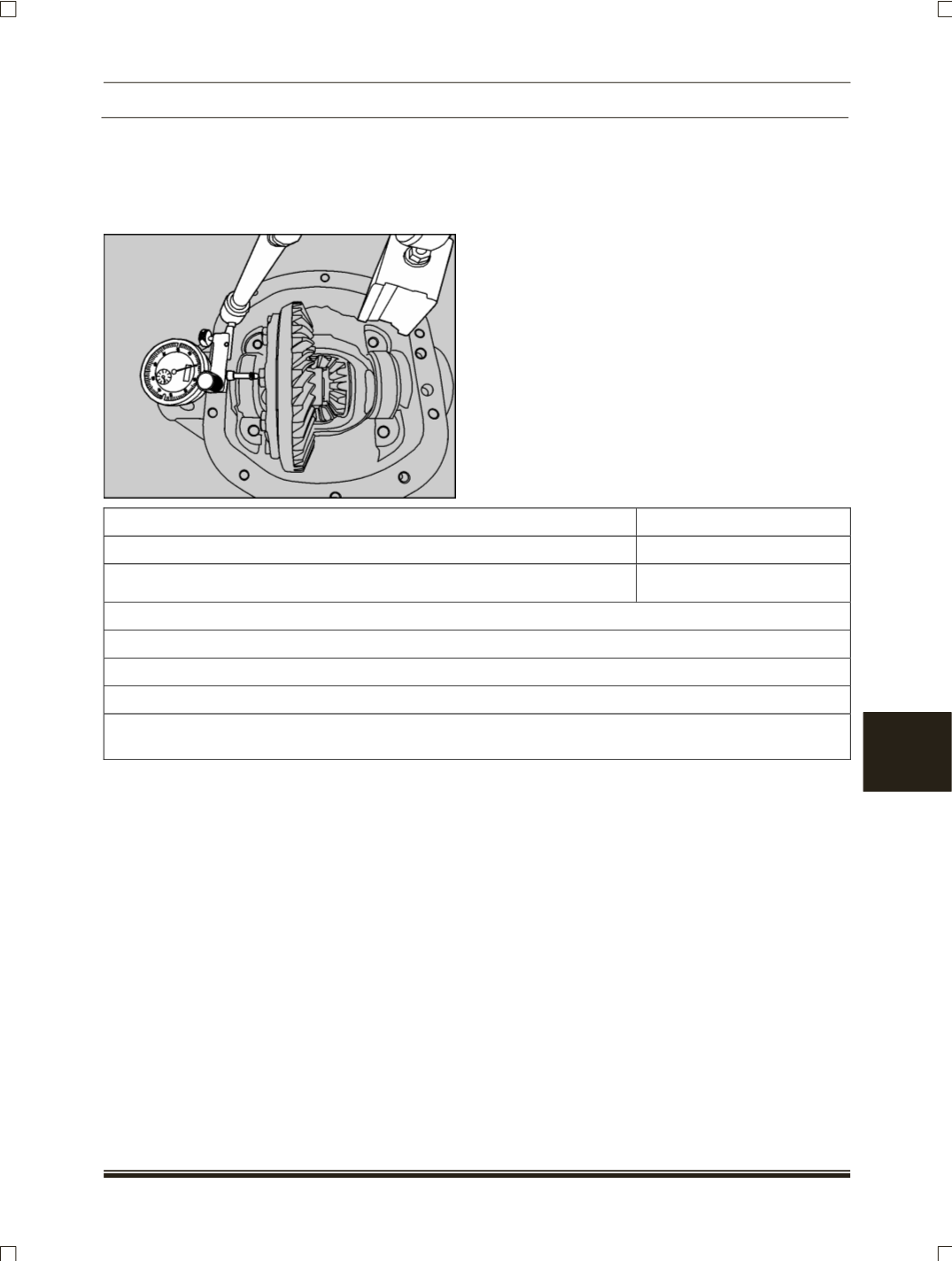
22.Place differential assembly into housing. Install
dial gauge and locate tip of indicator on the sur-
face of one of the ring gear screws. Force
differential case assembly away from pinion gear.
With force still applied set indicator at 0
(Zero)
.
23.Force differential case assembly and ring gear to
mesh with pinion gear.
24.Rock the ring gear to allow teeth to mesh Repeat
to obtain a stable reading. Record in given format
as B.
1. Total amount of space measured without ring gear.
Measurement A =………
2. Total amount of space measured with gear. set assembled in carrier
Measurement B=………
3. Measurement A minus Measurement B dimensions
Measurement C =………
Assemble shim pack using dimension determined in A, B, C adjusting the packs as described below.
RING GEAR SIDE
Assemble shim pack to measurement B- 0.125mm or B- 0.005”
OPPOSITE SIDE OF RING GEAR:
Assemble shim pack to measurement C. Add shim thickness 0.20 mm or 0.008” for differential bearing
preload and backlash.