


 533 / 1235

FRONT AXLE (4X4)
34
13.Assemble dummy differential bearings
(Part No.
270458903309)
in to the differential case
using
dolly
(Part No. 270458903325).
14.Assemble differential case into carrier.
(Without
Ring Gear.)
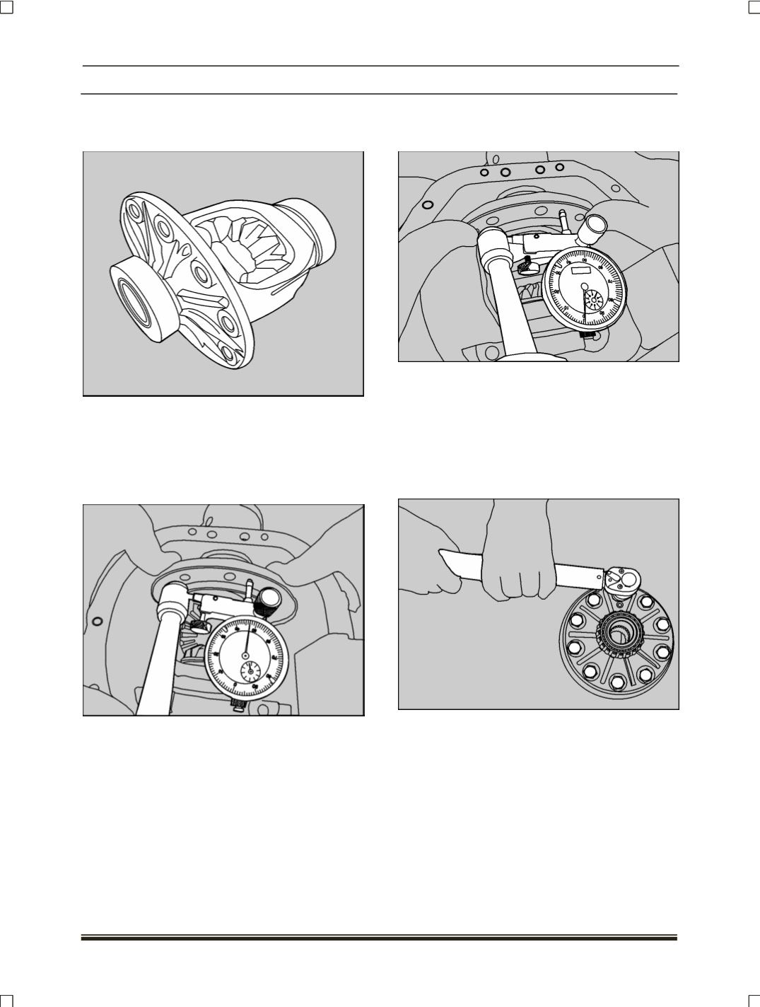
15.Mount dial indicator with a magnetic base. Locate
its tip on that surface of case and force differential
assembly to the extreme in the direction towards
the indicator.
16.With force still applied, set indicator to zero.
Force differential assembly to the extreme end in
opposite direction.
17.Repeat above steps until the same reading is ob-
tained.
18.Record reading in the format given as 'A'.
19.Remove dummy bearings
(Part No. 2704 5890 33
09)
and set aside.
20.Assemble ring gear to case. Torque ring gear
screws to specification.
NOTE
Use new ring gear screws at the time of assembly.
21.Again assemble master differential bearings
(Part
No. 2704 589 033 09)
on to differential case.