


 423 / 1235

TRANSFER CASE
35
TANSFER CASE
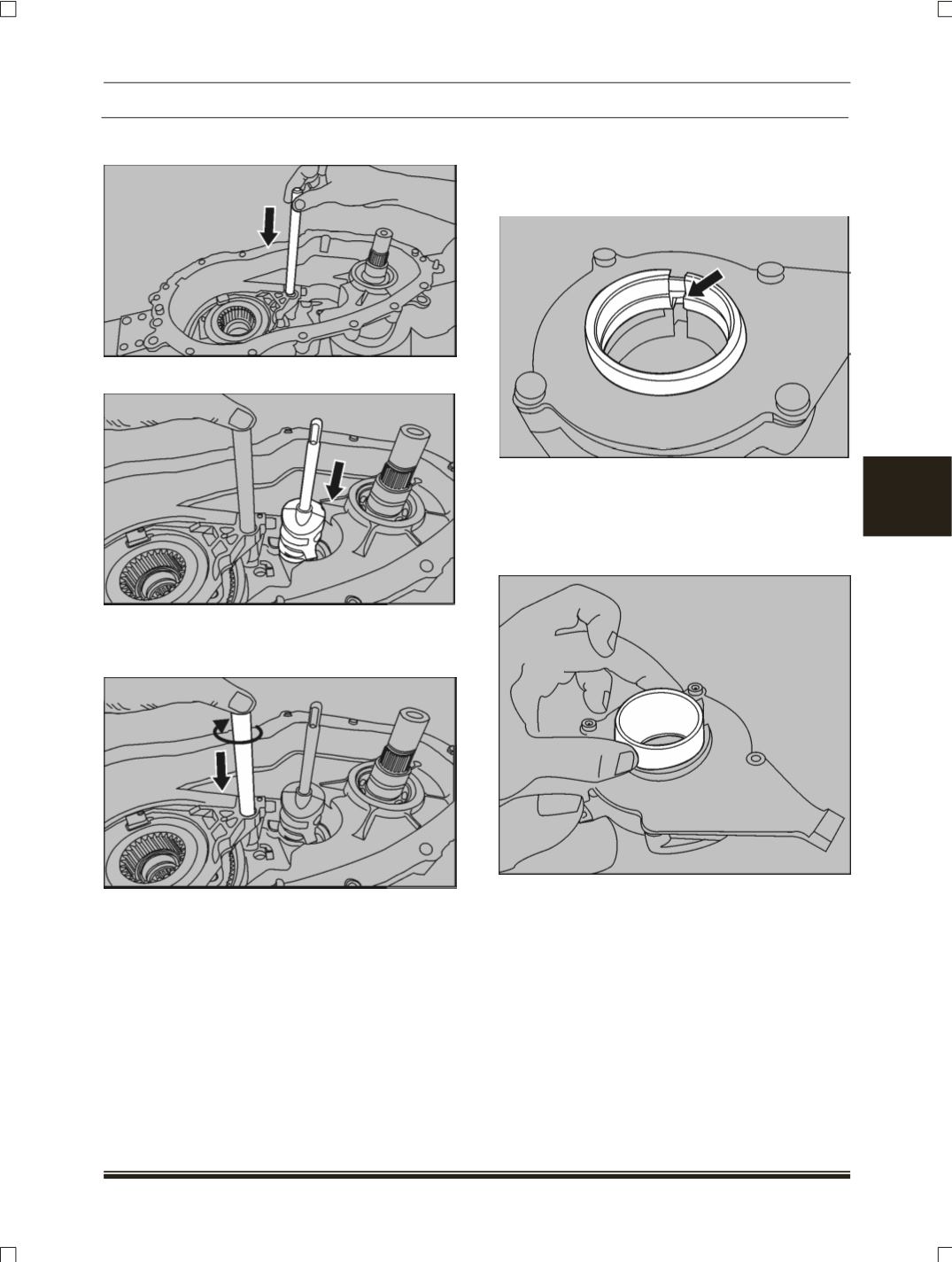
2. Insert the rail shaft into the case.
3. Insert the shift shaft in to the case
4. Carefully engage the reduction hub and
reduction fork assembly with the shift shaft
cam assembly.
D. ASSEMBLY OF OUTPUT SHAFT &
GEROTOR PUMP
1. Align rotor slot of the pump and slot of the
pump body in line.
NOTE
Use key aligner for inserting rotor assembly on to
the output shaft. The slot of the rotor should be
inline with the sleeve on to the output shaft as
shown in next step.