


 149 / 1235

ENGINE
117
2.1.6 LUBRICATION SYSTEM
2.1.6.1. SYSTEM DESCRIPTION
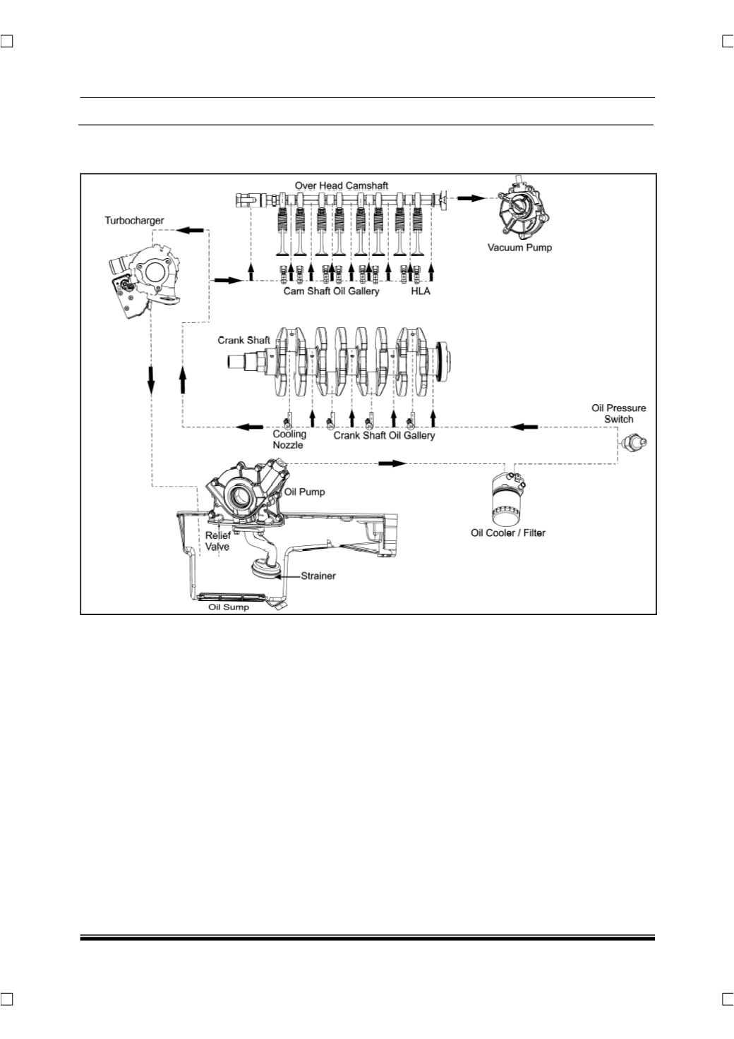
The lubrication system layout is as shown in the
schematic above. The oil pump is mounted on the
crankshaft pulley side. Oil is drawn up from the sump
through oil pump strainer and passes through the
pump to the oil cooler and then to the filter.
The filtered oil flows through the internal drilled holes
into the crankshaft oil gallery from here it is supplied
to connecting rod bearings and also to the main
bearings by means of intersecting passages drilled in
the crankshaft. It is then injected through the cooling
nozzle to the under side of the piston to cool it.
One more path takes the oil up from the crankshaft
oil gallery to camshaft oil gallery in cylinder head and
lubricates the camshaft. The camshaft oil gallery also
provides the oil needed by the HLA. There is sepa-
rate line that goes from the cylinder head to lubricate
the turbocharger and the return line is connected to
the cylinder block. The relieved oil drains back to oil
sump.