


 713 / 1428

ELECTRICAL
701
ELECTRICAL
REMOVAL
1. Disconnect the electrical connection
2. Loosen the locking nut & take out the switch
INSPECTION :
Brake lights (stop lights) are activated by a
mechanical switch on the brake pedal.
To test a suspected bad stoplight switch, bypass it
with a jumper wire. The stoplights should light when
the wires are connected. Use the test light to see if
there is power at one of the lights.
•
If the lights come on when the wires are connected
but not when the brakes are applied, replace the
switch.
•
If the stoplights operate without the key on,
remove the stoplight fuse before removing the
switch.
•
If the new switch is adjustable, adjust it so that it
is open when the pedal is released. The lights
should come on about 1/4" after the pedal is
applied. Also for switch adjustment details, refer
brake section.
REFITMENT
1. Tighten the locking Nut.
2. Connect the electrical connection
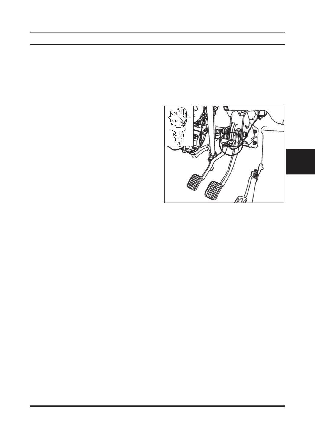
STOP LIGHT SWITCH
FUNCTION:
It sends signal to instrument cluster when the brake
pedal is pressed. This indicates operating of the brake.
LOCATION
It is located on bracket of brake pedal.
INSPECTION :
Test the switch with a Multimeter. Remove the rubber
grommet covering the door switch and remove one of
the electrical lead wires of the switch from its
terminals. Clip one probe of the VOM to each switch
terminal and shut the door. If the meter reads zero,
the switch is working. If the meter reads higher than
zero, the switch is faulty and should be replaced.
REFITMENT :
1. Fit the door switch screw.
2. Fit the rubber grommet.
3. Connect the electrical connection.