


 705 / 1428

ELECTRICAL
693
ELECTRICAL
REFITMENT :
1. Connect all electrical connectors of combi switch
assembly.
2. Fit combi switch assembly on steering column
are and tighten the screw.
NOTE :
Two lock ribs are provided on the steering
column, which will fit into the combi switch slots, to
avoid the rotation of switch & ensure proper fitment
3. Fit both steering column panels/nacells.
4. Fit steering wheel.
NOTE: Ensure that side levers are fitted in their
respective place and correct connectors are connected.
CAUTION: When tightening upper tray cover, ensure
that combination switch wires are not caught between
the covers.
STALKREPLACEMENT PROCEDURE
1. Remove the combi-switch. Refer removal &
refitment of combi –switch.
2. Remove the 2 screws & pull out the stalk.
3. Replace with new one.
4. Follow the step in reverse for refitment of stalk.
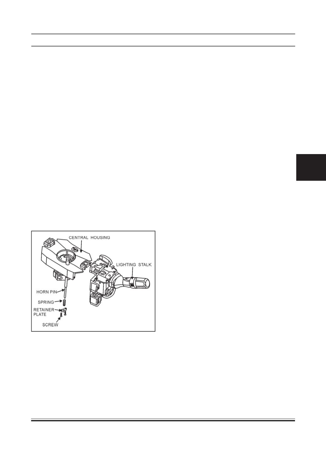
HORN PINREPLACEMENT:
1. Remove two screws of Horn locking pin from
Central Housing.
2. Remove spring alongwithworn out pin and replace
NewHorn pin with the same spring, Retainer plate
& screws.
3. Apply Electrical grease in the grease pocket of
Horn pin.
4. Assemble the socket terminal with horn pin.