


 422 / 1428

416
DRIVETRAIN
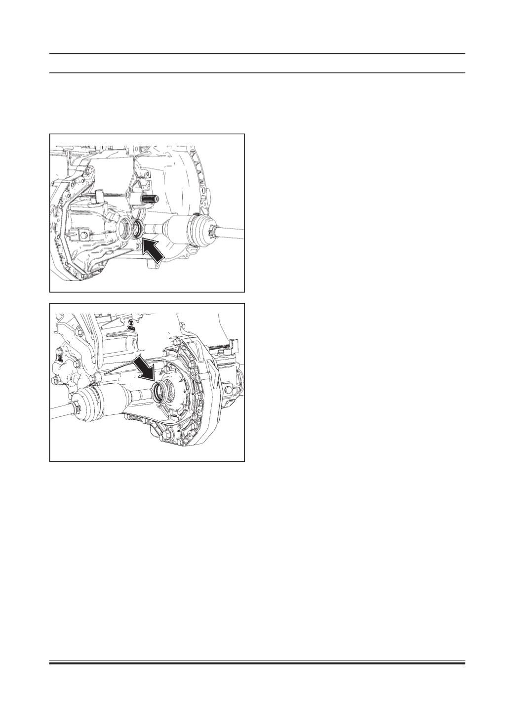
NOTE :
Whenever the driveshaft is removed (either LH or
RH side) the oil seal (as shown by arrow) must be
replaced.
Installation of driveshaft on vehicle
1. Align and insert the driveshaft properly into wheel
hub housing.
2. Keep the driveshaft in horizontal position such that
the splines of the driveshaft (transaxle end) match
with transaxle.
3. Align and insert the driveshaft properly into the
transaxle.
4. Lift the support up (by lowering the hoist) in such
a way that shock absorber lower mounting bolt
aligns with semi trailing arm frame.
5. Hand tighten shock absorber lower mounting bolt.
6. Remove the support and tighten shock absorber
lower mounting bolt to specified torque.
TIGHTENING TORQUE FOR SHOCK ABSORBER
BOLTS = 4 Kg-m
7. Tighten the inner mounting bolt of semi trailing arm
to specified torque.
TIGHTENING TORQUE FOR SEMI TRAILING ARM
CRADLE BOLTS = 8 Kg-m
8. Tighten the axle nut to specified torque.
TIGHTENING TORQUE FOR AXLE NUT = 17 Kg-m
9. Fit wheel(s) and tighten wheel bolts to specified
torque. Remove stands and lower vehicle.
TIGHTENING TORQUE FOR WHEEL BOLTS = 8 -
8.3 kg-m
10.Top-up transaxle oil.
NOTE :
1. During the whole process of installing the drive
shaft on vehicle, the boot and machined surface
should never contact any component of the
vehicle.
2. All precautions should be taken to avoid damage
to threads and splines of the joint.