


 308 / 1428

302
ENGINE 273 MPFI
BLINK CODE
Blink code is a symbolic representation of a recorded
fault; it is displayed by blinking the MIL in the
instrument panel. It is a crude method and is used
where TML diagnostic tool is not available.
Sensors fault diagnosis:
Make sure that the ignition key is in ON and engine is
not cranked, i.e. RPM=0. Then
Insert Short link into the OBD connector located under
the steering column.
After 7 seconds ECU recognizes for blink request and
blinks as per table 1: Blink code details.
Short link:
The short link will short the pins of two pole connector
- one is K-line and other is Ground. On shorting these
pins ECU recognizes the blink code request and
activates the blink code.
Blink Code Representation:
The ON/OFF pulse of the MIL for fault codes
combinations:
1. No fault recorded in ECU: 0.5 sec ON followed by
0.5 sec OFF in cyclic way.
Note:
Do not short the pins at OBD connector
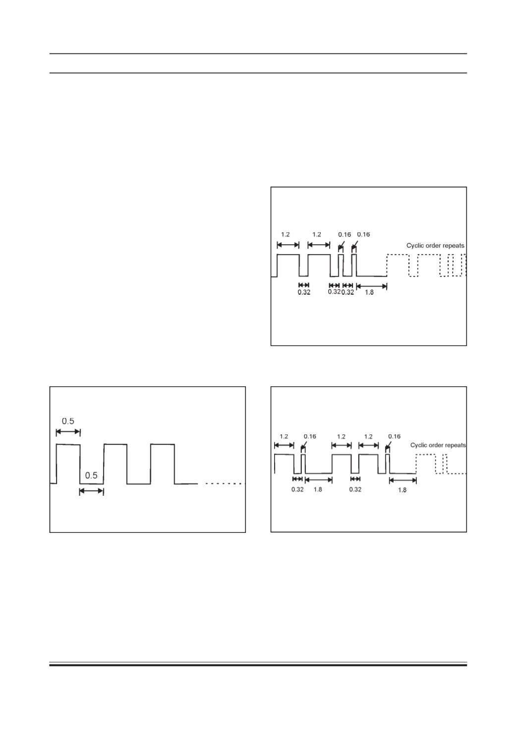
2. One fault code is logged in ECU: Each big pulse
(1.2 sec) represents 10 counts and small pulse (0.16
sec) represents 1 count.
Blink code 22 is represented by 1.2 sec ON then 0.32
OFF and then 1.2 sec ON then 0.32 OFF then 0.16
sec ON then 0.32 OFF then 0.16 sec ON followed by
1.8 second inter blink code gap after that the same
sequence is repeated again.
The same pattern repeats as shown.
3. Multiple fault codes are logged in ECU: Example:
Two fault codes 11 and 21 are logged.
OBD / Diagnostic Connector Location:
The OBD connector / 16 pin connector / short link coupler / test switch is located on the relay panel, which is
mounted onA-pillar