


 692 / 1980

680
ELECTRICAL
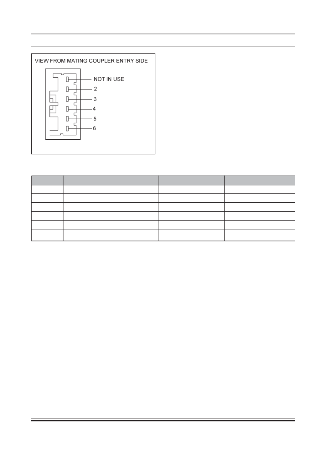
For connector pin details refer below table
1.
LOCK:
When master actuator moves to lock
position it will give lock signal to ECU Pin. No. 2
Then ECU sends a lock pulse on lock Output pin
of ECU Pin no. 6 it locks all actuators.
2.
UNLOCK:
When master actuator moves to unlock
position it will give unlock signal to ECU pin No.
2 .then ECU send an unlock pulse on unlock
output pin of ecu pin No. 4 it unlocks all actuators
Note:
same Pin No. 2 is being used for sensing
lock/unlock signal for micro controller.
3. For Moving plunger of actuator from “OUT” position
to “IN” the pin no. 6 gets connected to +ve supply
& pin no. 4 gets connected to –ve supply from the
controller. In this condition micro switch contacts
“C”& “NO” are closed and “C” & “NC” are open.
The above polarities and micro switch contacts
get reversed for the return stroke from “IN” to “OUT”.
PRELIMINARYCHECKS
Carry out the following preliminary checks as per given
order before starting the repairs.
•
Check fuse. Replace blown fuse, if any.
•
Check battery condition and state of charge.
Recharge or replace battery as required.
•
Check all related electrical connections including
earth connection for cleanliness and proper
gripping. Check specially the control unit earth
connection. Rectify as required.
•
Operate driver’s side door lock from inside and
outside and check functioning of central locking
system. Locate the faulty unit and carry out
repairs as given in subsequent paras.
•
If the central locking system is found inoperative
in total, check for the power supply at control box
input end. If this is OK, remove the control unit
and check for proper functioning on the rig.
PIN NO.
SIGNAL DESCRIPTION
ACTIVE LEVEL
INPUT/OUTPUT
1
Not used
-
-
2
Lock/Unlock feedback
Active Low/High
I/P
3
Battery Negative
+0 v
I/P
4
Unlock Output
+12 v Pluse
O/P
5
Battery Positive
+12 v
I/P
6
Lock Output
+12 v Pluse
O/P