


 497 / 896

BRAKE SYSTEM
505
BRAKES
2. ADJUSTMENTS :
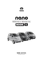
2.1 Stop light switch adjustment
Stop light switch adjustment should be done as
follows while installation
Pull up brake pedal towards you and while holding it
there, adjust switch position such that clearance
between end of thread and brake pedal return cushion
(shown by “a “ ) will be as per specified value.
“a” = 2.5 ± 0.5 mm
Brake pedal return cushion
Stop light
switch nut
Stop light
switch
NOTE:
(a) If adjustment value exceeds than the specified
value, it may cause non – actuation of stop light
switch.
(b) If adjustment value is less than the specified value,
it may lead to dragging of brakes, loss of fuel
efficiency and in worst cases damage to brake
system.
2.2 Brake pedal free height adjustment (only for
booster fitted vehicle)
Height of brake pedal is normal if it is about 10 mm
lower than clutch pedal.
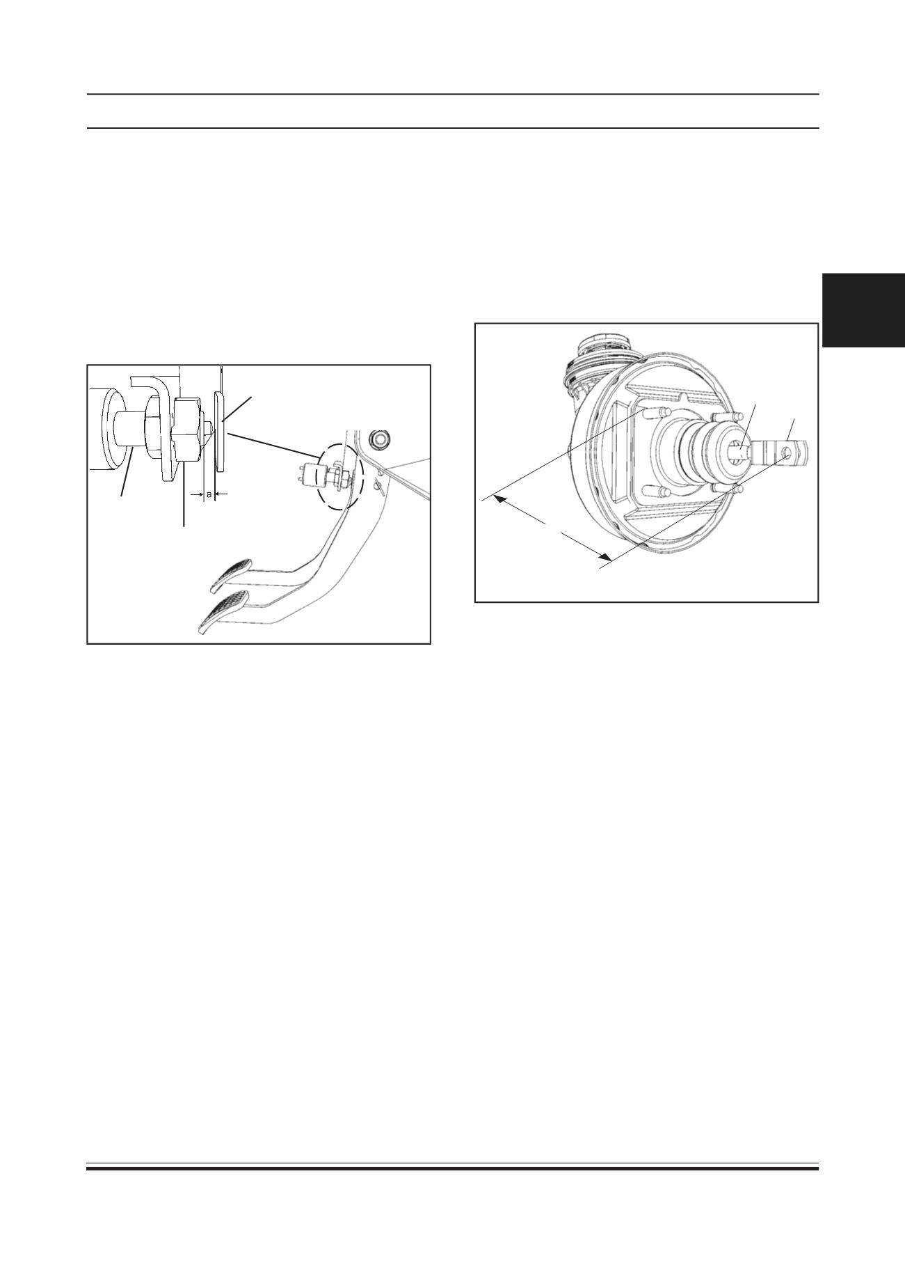
(i) When booster push rod clevis has been rein-
stalled it is important that measurement between
booster mounting surface and center of clevis pin
hole is adjusted.
a
1
2
1. Push rod clevis
2. Push rod nut
Length “a” = 120 mm
(ii) When brake stop light switch has been removed,
stop light switch should be adjusted. (Refer stop
light switch adjustment)
Services in above steps (1) and (2) may affect
brake pedal height.
NOTE:
Improper adjustment value may lead to change in
brake pedal position, dragging of brakes and loss of
fuel efficiency.