


 257 / 1006

ENGINE 273 MPFI
251
ENGINE
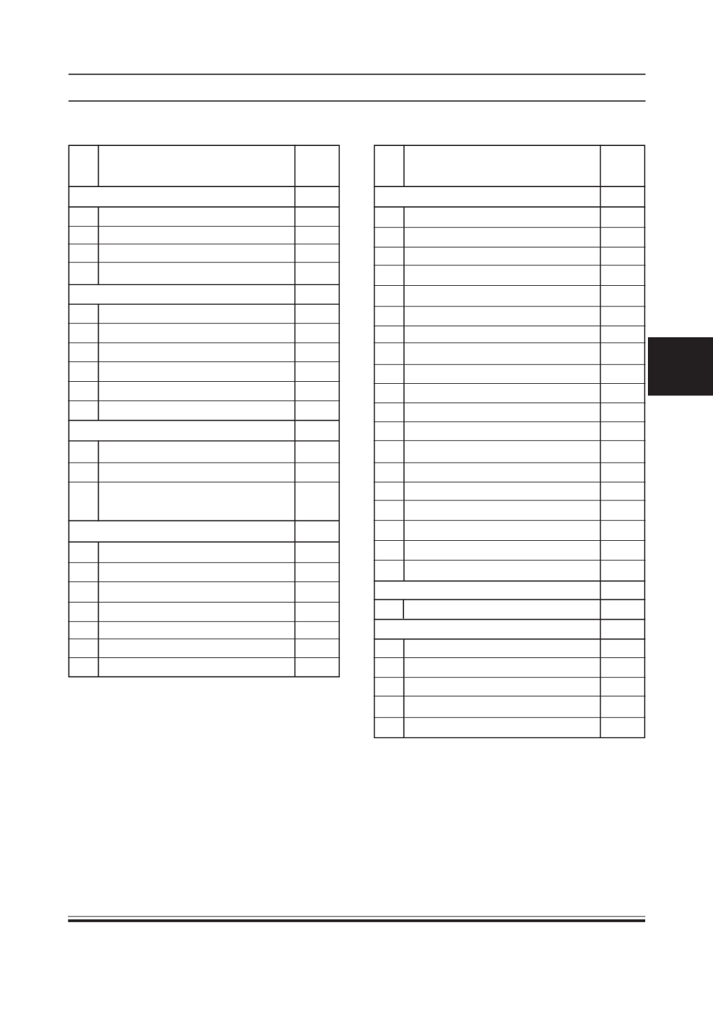
ECU Pin Assignment Details:
Pin Signal
Wire
No
Colour
Power Feeds
9 Ignition Switch
Y/R
6 Throttle Position Sensor Supply BR/G
7 Manifold Pressure Sensor Supply V/R
53 Battery Input Voltage
R
Grounds
30 Water Temperature Sensor Ground BR/W
31 UpstreamOxygen Sensor Ground V
42 Manifold Pressure Sensor Ground W/G
50 Battery Ground 3
BR
51 Battery Ground 1
BR
52 Battery Ground 2
BR
Inputs – Digital
28 AC Request Input
L
45 Vehicle Speed Sensor
R/W
40 Reverse Gear Input for CVT
-
Application
Inputs – Analog
10 Throttle Position Sensor
V
11 Reserve Pin
-
12 DownstreamOxygen Sensor
-
22 Manifold Pressure Sensor Signal
W/O
24 ManifoldAir Temperature Sensor
W/Y
27 Crank Shaft Sensor -
P
29 Knock Sensor (Package Protected)
-
Pin Signal
Wire
No
Colour
Outputs - Digital
2 Main Relay Driver
Y/BR
3 CKNL
Y
4 Cooling Fan Relay Driver 1
W/B
5 Injector 1
L/G
8 Reserve Pin
-
14 UpstreamOxygen Heater
P
15 Canister Purge Driver
Y/L
16 Injector 2
Y/G
18 AC Compressor Relay Driver
GY/W
19 Fuel Pump Relay
W/G
20 Coolant Temperature Output
G/L
21 Reserve Pin
25 Stepper Driver D
LG/O
26 Stepper Driver C
R/L
37 Stepper DriverA
G/R
38 Stepper Driver B
W/V
49 AC Fan Relay
G/R
54 Reserve Pin
-
55 Ignition Coil
L
Outputs - Analog
-
-
-
Communication
34 K Line
R/G
35 CAN - Application
-
36 CAN +
-
47 CAN + Application
-
48 CAN -
-