


 634 / 1904

622
ELECTRICAL
Rectifier assembly check:
Remove the rectifier assembly from the unit and
check as follows:
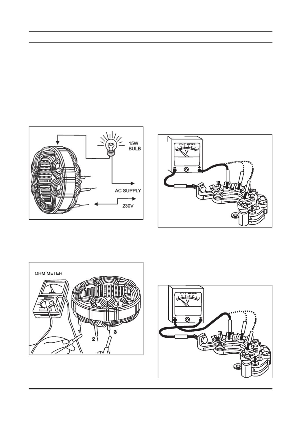
(a) Testing of positive heat sink diodes
(i) Continuity check
Connect as shown in figure 55. Use multimeter
with two probes. Connect the negative probe of the
multimeter to positive terminal and positive probe
to phase connecting points one by one on the
rectifier assembly. It should not indicate open
circuit. Replace the rectifier assembly if it is open
circuit.
(ii) No Continuity check
Connect as shown in figure. Use multimeter with
two probes. Connect positive probe of multimeter
to positive terminal and negative probe to phase
connector points one by one on the rectifier
assembly. All diodes should indicate no continuity.
If there is continuity it indicates short circuit.
Replace the rectifier assembly
Using 230 volt AC main supply connect a 15W
bulb as shown in figure. Connect one of the probes
to the slip ring and the other to the shaft. The lamp
should not glow. If the lamp glows it indicates
earthing. Replace the rotor assembly.
•
Stator insulation test:
Using 230 volt AC main supply connect a 15W
bulb, Connect one of the probes to any of the three
leads and the other probe to the body. The lamp
should not glow. If the lamp glows it indicates poor
insulation. Replace the stator assembly.
•
Stator winding resistance check
Use Ohm meter with two probes connect lead 3
and lead 1. The Value should read around 0.180 to
0.202 Ohms at 20°C. Repeat it between star
connection and lead 2 and 3.