


 466 / 1904

460
SUSPENSION SYSTEM
Inspection:
1. Inspect semi trailing arm assembly for any me-
chanical damage or crack. Replace if found dam-
aged.
2. Inspect the condition of bushes. Replace the same
if found cut or signs of wear.
Installation:
1. Align the semi trailing arm on cradle and hand
tighten inner and outer pivot bolts.
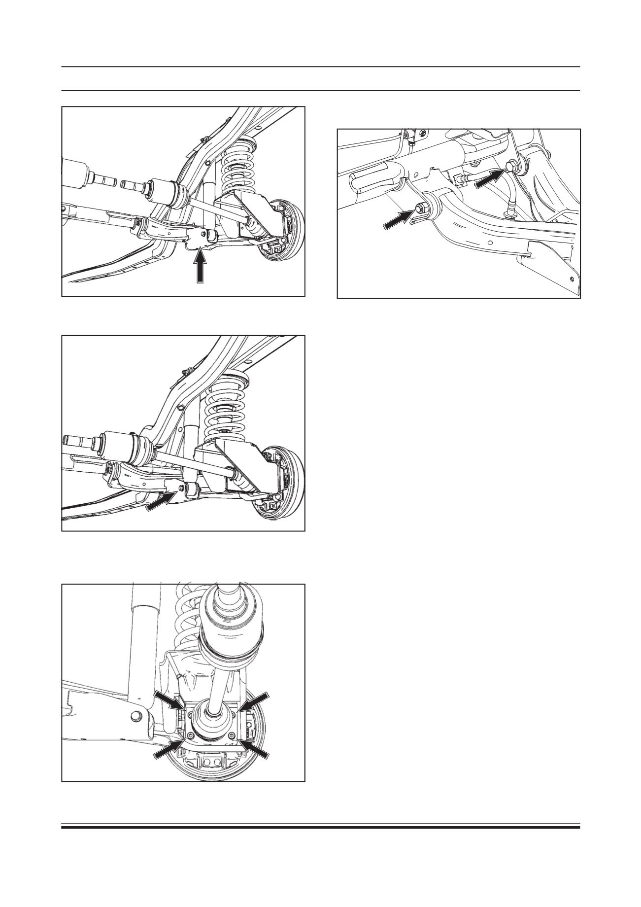
2. Mount the anchor plate and brake drum assembly
and tighten four allen bolts of rear hub unit to speci-
fied torque.
TIGHTENING TORQUE OF MOUNTING BOLTS OF
WHEEL HUB UNIT = 5 Kg-m
3. Fit the drive sha
ft and tighten wheel lock nut to
specified torque. Fix thrust washer and hub cap.
TIGHTENING TORQUE FOR WHEEL LOCK NUT = 17 Kg-m
4. Lift the support (by lowering hoist) in such a way
that shock absorber - lower mounting bolt aligns
with semi trailing arm frame.
5. Hand tighten shock absorber lower mounting bolt
(07)
6. Remove the support and tighten semi trailing arm -
inner and outer pivot bolts and shock absorber -
lower mounting bolt to their specified torque in non-
loaded condition.
TIGHTENING TORQUE FOR SEMI TRAILING ARM
CRADLE BOLTS = 8 - 8.5 Kg-m
TIGHTENING TORQUE FOR SHOCK ABSORBER
LOWER MOUNTING BOLT = 3.5 - 4 kg-m
7. Install coil spring.
7. Remove four mounting allen bolts of rear hub unit
and take out brake drum alongwith anchor plate.
Disconnect driveshaft.
8. Remove semi trailing arm inner and outer pivot bolts
NOTE:
Support the driveshaft properly.
6. Remove the lower mounting bolt (07) of shock
absorber (05).
Support