


 462 / 1904

456
SUSPENSION SYSTEM
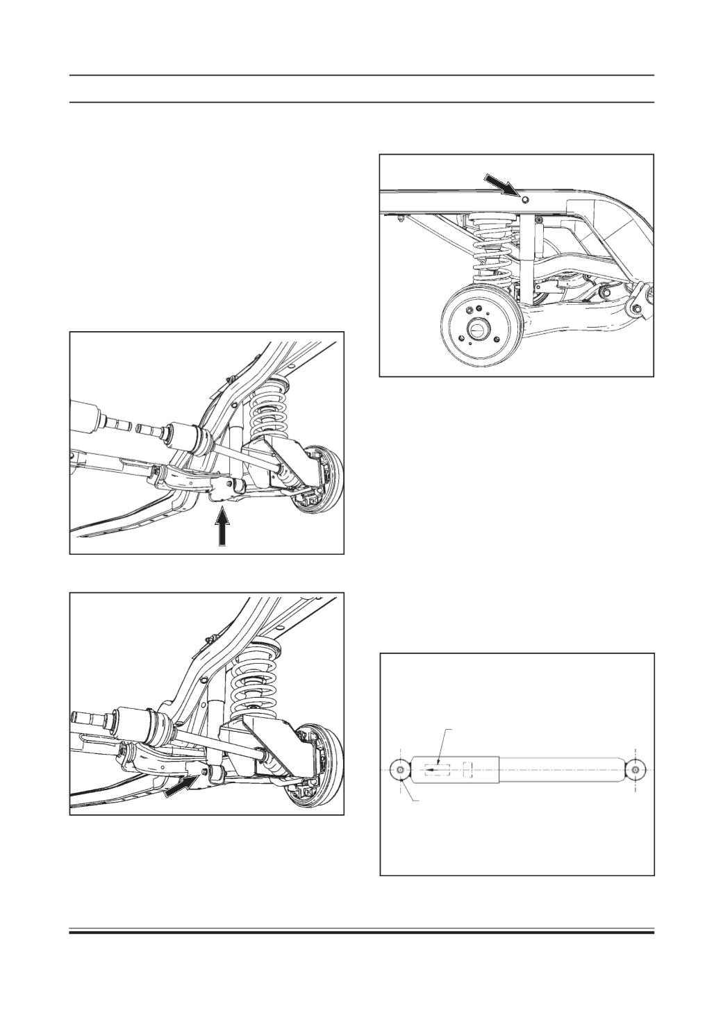
White sticker arrow as shown
(For mounting orientation)
Both ends
identical
SHOCK ABSORBER
NOTE:
Refer Exploded view of Rear Suspension
Components for removal and installation process.
Removal
1. Remove wheel(s) (Refer wheel removal procedure/
Wheels and Tires group)
2. Support the semi trailing arm (01) (as shown below
by arrow in fig. given below) so that:
(a) It will keep the semi trailing arm from flying
downward when the shock absorber is unbolted.
(b) Drive shaft angles are not exceeded.
3. Remove the lower bolt (07) of shock absorber (05).
4. Remove the upper bolt (11) of shock absorber and
take out the shock absorber (05).
CAUTION :
Hold the shock absorber while removing
the bolt.
Inspection:
1. Check the removed shock absorber for oil strains
and bush damage/any scratch marks for rubbing
of dust cover and outer tube. Replace the damaged
parts.
2. Ensure shock absorber orientation such that dust
cover is on top side.
3. Inspect shock absorber for any deformation or
damage. Replace if found damaged.
Installation
CAUTION:
Before installing shock absorber please
see the white sticker on shock absorber which
indicates the correct direction of mounting.