


 740 / 1575

ANTI LOCK BRAKING SYSTEM (ABS)
16
6.2.2 REPAIRS
PRECAUTIONS
1. Before undertaking any electric arc welding
work, disconnect the ABS ECU's connector.
2. During paintwork operations or major repair
work, which are likely to subjected to higher
temperature (above 85° C), The HCU must be
removed.
3. Before removing the ECU, the battery must be
disconnected. Terminals must be fully tightened
while installing battery.
4. Electrical wiring should not to be repaired it
should be replaced.
!! WARNING
When the hydraulic connections to the hydraulic
modulator can be crossed over; the ECU self-
diagnosis will not detect it as a fault; nor will it cause
the system to be shut down or cause a fault code to
be logged in the ECU. When the hydraulic modulator
is exchanged or repaired, the brake pipes to the
solenoids must be tested for correct assignment
using a diagnostics tester. When the inlet and outlet
valve are activated, e.g. on the front left wheel, this
must generate the necessary changes at the wheel.
If this does not happen, the pipes have been crossed
over. This will cause the system to function
incorrectly.
BRAKE SYSTEM BLEEDING
NOTE
For brake bleeding procedure conventional/ using
diagnostic tool refer Brakes group.
A. ABS ECU / HCU
REMOVAL
1. Turn OFF the ignition switch and disconnect
battery.
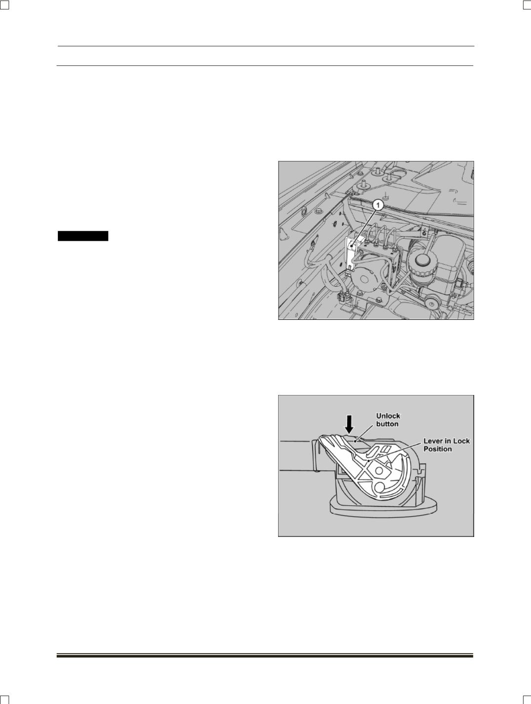
2. Disconnect ABS ECU/HCU wiring harness
connector (1)
(Refer the procedure given in the
note below).
NOTE
Refer steps (i) and (ii) to disconnect ABS ECU /HCU
connector.
(i) Press the unlock button and remove the lever
from the lock and move towards unlocking
position.