


 738 / 1575

ANTI LOCK BRAKING SYSTEM (ABS)
14
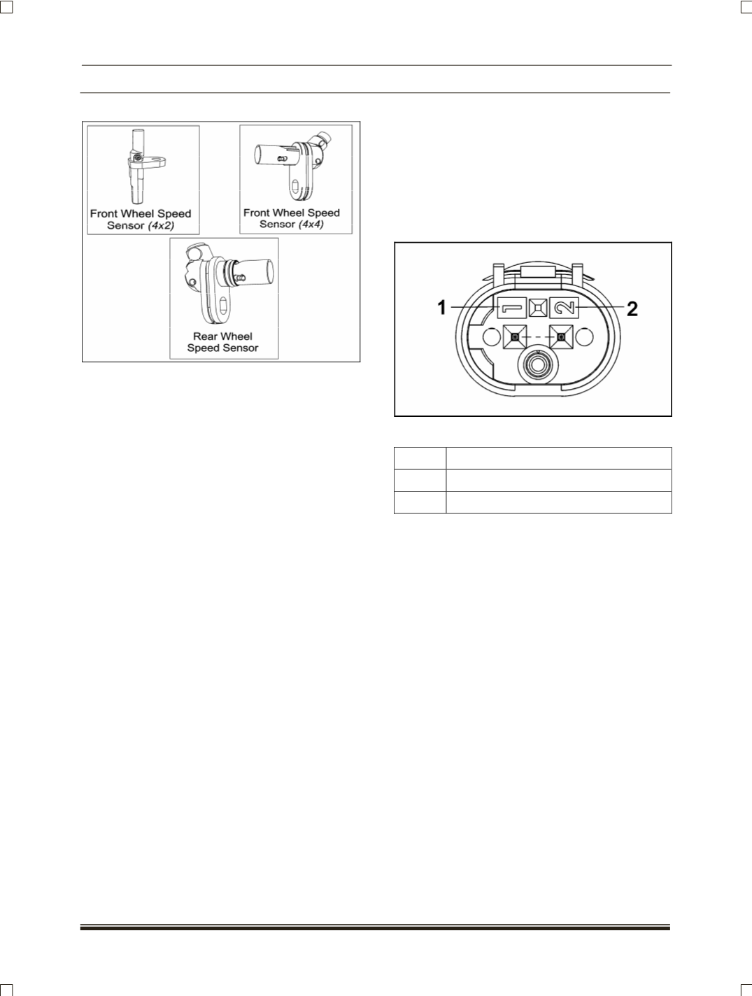
B. WHEEL SPEED SENSOR
(WSS)
WORKING PRINCIPLE
The Wheel speed sensor in this vehicle is connected
to a voltage source for operation
(active sensor)
. It is
used in conjunction with a ferrous Toner wheel and
supplies a signal with constant amplitude pulses
whose frequency varies with the wheel speed. It
uses Hall Effect principle, it has a semiconductor
chip with the electronic circuit for supply and signal
processing integrated on it.
This chip is located within an almost completely
insulated magnetic circuit consisting of permanent
magnet and pole elements. The wheel speed sensor
is mounted directly above the non-magnetized toner
wheel. The toner wheel is a ring with teeth on it. The
toner wheel is fitted on to the wheel hub. The
alternating teeth and gap that accompanies the
wheel rotation induces differential magnetic flux
density, thus leading to the variation in the voltage
induced in the semiconductor chip. The signal
conditioning circuit converts this voltage variation
into constant amplitude current pulses. The
frequency of these pulses depends up on the wheel
speed. This measurement principle permits zero
speed measurement
Precise alignment and gap between the stator pole
and the Toner wheel is vital. To obtain correct signal,
the specified gap between the end of sensor and the
toner ring must be maintained.
Refer Repairs section for procedure to check air gap.
PIN OUT
PIN DETAILS
PIN NO.
DESCRIPTION
1
Wheel Speed Sensor Signal
2
Wheel Speed Sensor Power
Precautions while handling wheel speed sensor
1. Storage temperature
(- 40° C to + 50° C)
should
not be exceeded
2. Avoid free fall of the sensor
3. The sensor tip should not be scratched.
4. Sensor should not be exposed to strong
magnetic field.