


 196 / 1575

ENGINE
157
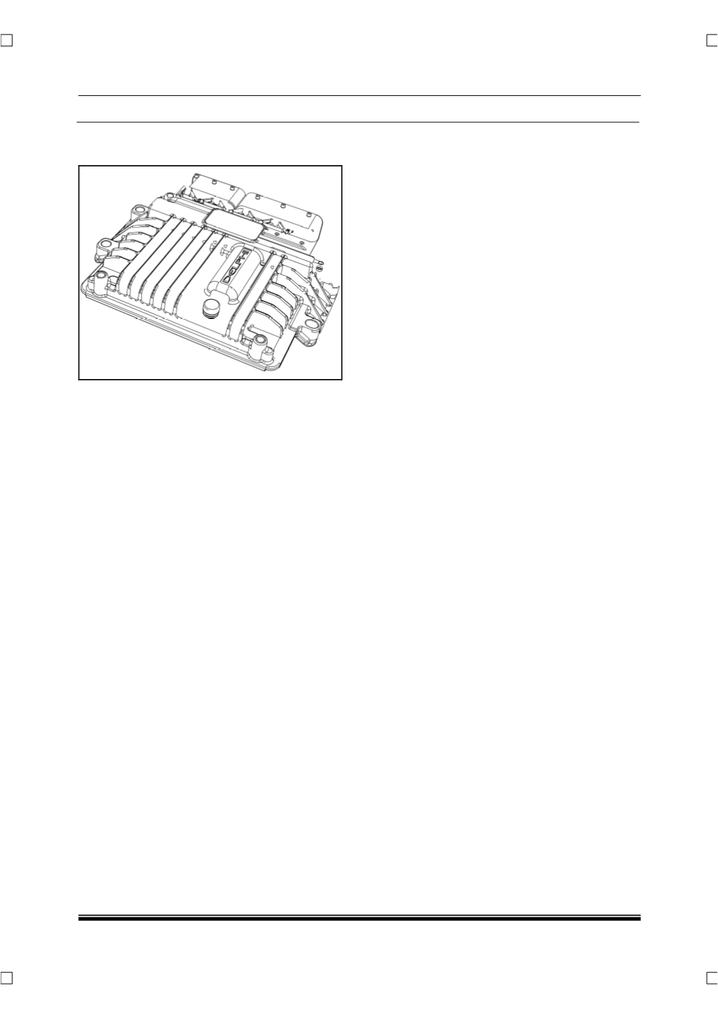
2.1.9 ENGINE MANAGEMENT SYSTEM
(EMS)
DESCRIPTION
Engine Management System (
EMS
) comprises of
Electronic Control Unit (
ECU
), sensors, actuators
and control algorithms that determine the perfor-
mance of the Engine as a whole and as part of the
vehicle.
The Electronic control Unit consist of a 32 bit micro-
processor with peripheral devices like ignition driver,
ADCs device and I/O drivers. Microprocessor con-
trols the injection parameters as well as some of the
vehicle related outputs such as Fan, AC, drivability,
turbocharger, EGR etc. The ECU receives input
from various sensors located on the engine and the
vehicle, and decides the injection quantity, injection
timing, number of injections best suited for the en-
gine to work with maximum efficiency and safety. It
is the ‘Brain’ of the Engine Management System.
Being the most important component of the Engine
management system, ECU apart from ensuring the
optimum working of the Vehicle, also keeps an eye
on the working of the sensors and actuators. When
ever a malfunction/fault occurs in the component or
the system the ECU alerts the user by glowing MIL
indicator on instrument cluster. ECU also does the
following:
•
Stores a DTC in its memory (
indicates the faulty
component/system
).
•
Stores a context frame (
list of parameters indicat-
ing the operating condition during the fault
generation
) in its memory.
•
When the malfunction poses a threat to the vehi-
cle, the ECU with its control algorithms operates
the vehicle in safe mode. This protects the com-
ponent from damage with some degradation in
performance of the vehicle.
•
EMS gets the vehicle electrical load via DF signal
and adjusts the Idling torque if necessary to meet
the electrical load requirements.
NOTE
For certain faults and for failure of some sensors the
EMS switches to reduced torque or limp home
mode. During this mode the vehicle performance
will be restricted and MIL lamp will be ON.
MAKE:
Delphi Diesel System
MODEL / TYPE:
DCM 3.7