


 1062 / 1575

ELECTRICAL
242
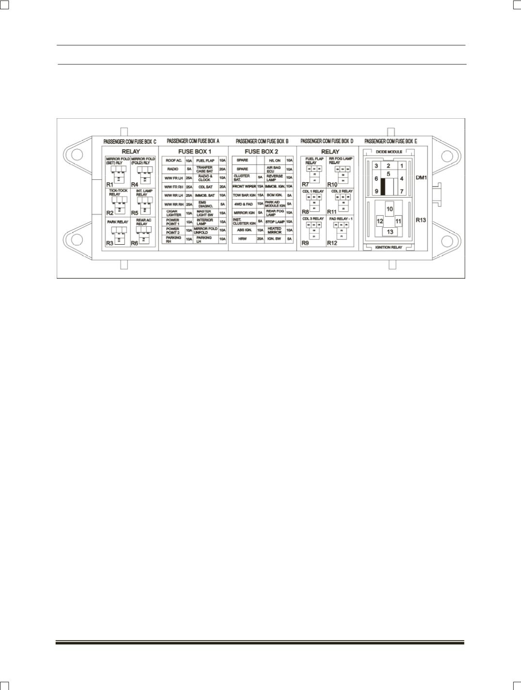
3. CABIN FUSE AND RELAY BOX:
This fuse box is part of main wiring harness. For details refer the below fuse box sticker fitted on
steering column lower cover. For other pin out details of fuse box refer the power distribution II circuit
schematics.
REPLACEMENT PROCEDURE FOR RELAYS
1. Turn the ignition key to lock position.
2. Check each relay, if faulty replace with same rating relay.
3. If replaced relay of same rating is not working properly, there is probably a serious electrical problem.
REPLACEMENT PROCEDURE FOR FUSES
1. Turn the ignition key to lock position.
2. Check each fuse and look for broken/open controls link wire inside the fuse. If it is burnt, replace it with
one of the spare fuses of same rating.
3. If replaced fuse of same rating burns out then, there is probably a serious electrical problem.
Note: Use designated fuses only
.
8.17.2 CIRCUIT SCHMATICS
Refer A3 Book
8.13.3 WIRING HARNESS FITMENT DRAWING
Refer A3 Book
8.17.4 DTCs
Refer A3 Book