


 165 / 745

KRYOTEC ENGINE
157
80. Install the fuel injection pump with bracket and
tighten the bolts to the proper (Torque
Specifications).
81. Install the alternator and tighten the bolts to the
proper (Torque Specifications).
82. Install the engine oil filter-heat exchanger with
NEW O-ring seals and tighten the screws to the
proper (Torque Specifications).
83. Install the centering bushing and bracket with
the bolt tightened to the proper (Torque
Specifications).
84.
Install the DPF bracket and tighten the
bolts to the proper (Torque Specifications).
85. Install the A/C compressor mounting bracket
and tighten the bolts to the proper (Torque
Specifications).
86. Install the A/C compressor and tighten the bolts
to the proper (Torque Specifications).
87. Install the engine oil cooler coolant outlet hose
and connect the quick couplings.
88. Install the engine oil cooler coolant inlet hose,
connect the quick couplings and secure the hose
to the support bracket.
89. Connect the fuel return hose to the fuel injection
pump and tighten the clamp to the proper (Torque
Specifications).
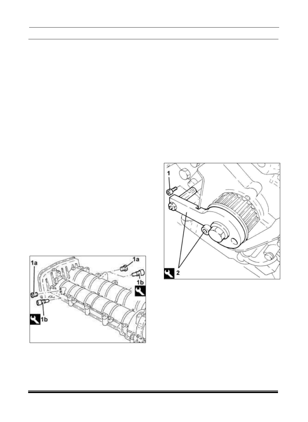
90. If not already done during inspection of the
cylinder head, remove the caps (1a) and install the
1870896900 camshaft timing tools (1b) in the
cylinder head cover.
NOTE
Verify proper installation of the 1870896900
camshaft timing tools.
91. Remove the intake side camshaft timing tool,
install the cap and tighten to the proper (Torque
Specifications).
NOTE
The cylinder head to cylinder head cover centering
bushings are longer (16.0 mm) compared to the
engine block to cylinder head centering bushings,
so be careful not to reverse them as engine
damage may occur.
92. Install the cylinder head cover centering
bushings in the cylinder head.
93. Install the rocker arms.
94. Install the cylinder head cover gasket.
95. Install the cylinder head cover and tighten the
bolts to the proper (Torque Specifications).
96. If not already done during inspection of the
cylinder head, loosen the exhaust camshaft pulley
bolt.
97. Remove the bolt (1).
NOTE
To allow insertion of the dowel pin through the hole
in the tool into the engine, turn the crankshaft with
small movements.
98. Install the 2000003000 engine timing tool (2).
99. Place the engine balancing module in its
housing, complete with spacers, and tighten the
corresponding screws.
100. Remove the balancing shaft locking pin
2016000090 and the crankshaft timing template
fitted previously.
101. Apply silicone sealant to the entire perimeter
of the engine oil sump.
102. Place the engine oil sump back in its housing.