


 367 / 801

BRAKES
45
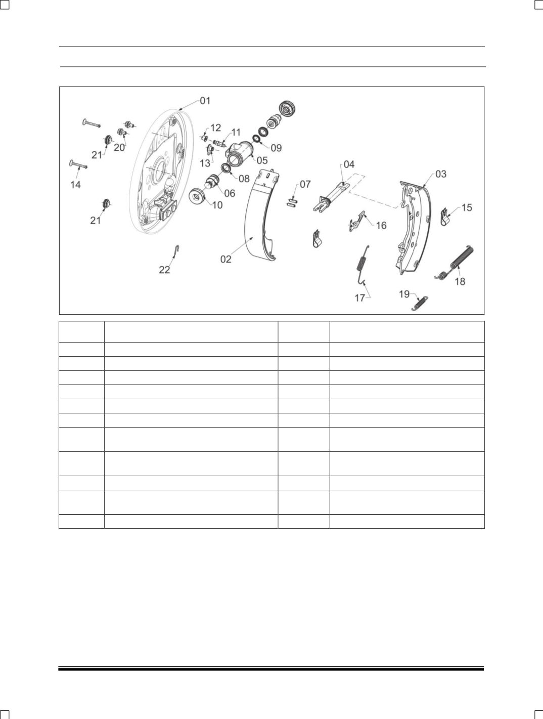
REAR BRAKE ASSEMBLY :
ITEM NO
DESCRIPTION
ITEM NO
DESCRIPTION
01
BACKPLATE ASSEMBLY
12
CAP, BLEED SCREW
02
LINED SHOE ASSY - LEADING
13
PROTECTIVE PLUG
03
LINED SHOE ASSY - TRAILING
14
PIN, SHOE HOLD DOWN
04
ADJUSTER ASSEMBLY
15
P-CLIP
05
WHEEL CYLINDER BODY
16
LEVER, PAWL
06
PLUNGER ASSEMBLY
17
SPRING, ADJUSTER
07
PIN
18
SPRING, SHOE RETURN W/CYL
END
08
SEAL
19
SPRING,
SHOE
RETURN
ABUTMENT END
09
SPRING W/CYL
20
SCREW, W/CYL MOUNTING
10
DUST COVER
21
GROMMET, LINING INSPECTION &
ADJUSTER HOLE
11
BLEED SCREW
22
CLIP
INTRODUCTION:
This brake is designed for use on rear wheels and
is equally efficient in both directions of rotation. A
mechanical lever mechanism is incorporated for
normal hand brake operation. The feature of this
brake is the automatic adjustment of the brake
shoes takes place when the foot brake is applied.
The leading and trailing shoes are connected at
one end by a twin-piston wheel cylinder and an
adjuster assembly. The adjuster assembly
consists of a male and female push rod with an
adjuster nut operated by a pawl.
Coupled on the trailing shoe is a hand brake
lever, which pivots on a pin at the wheel cylinder
end of the shoe.
A spring dowel fitted at the leading shoe provides
a pivot for the pawl, which is restrained in position
by a spring attached in the web. The hand brake
cable passes through a hole in the back plate
assembly (6), and the nipple fits in the end of the
hand brake lever. When the hand brake is
applied, the cable pulls the lever and this
movement is transferred via the adjuster
assembly (4) to the shoes, which move outwards
onto the drum.