


 654 / 1006

BRAKES
16
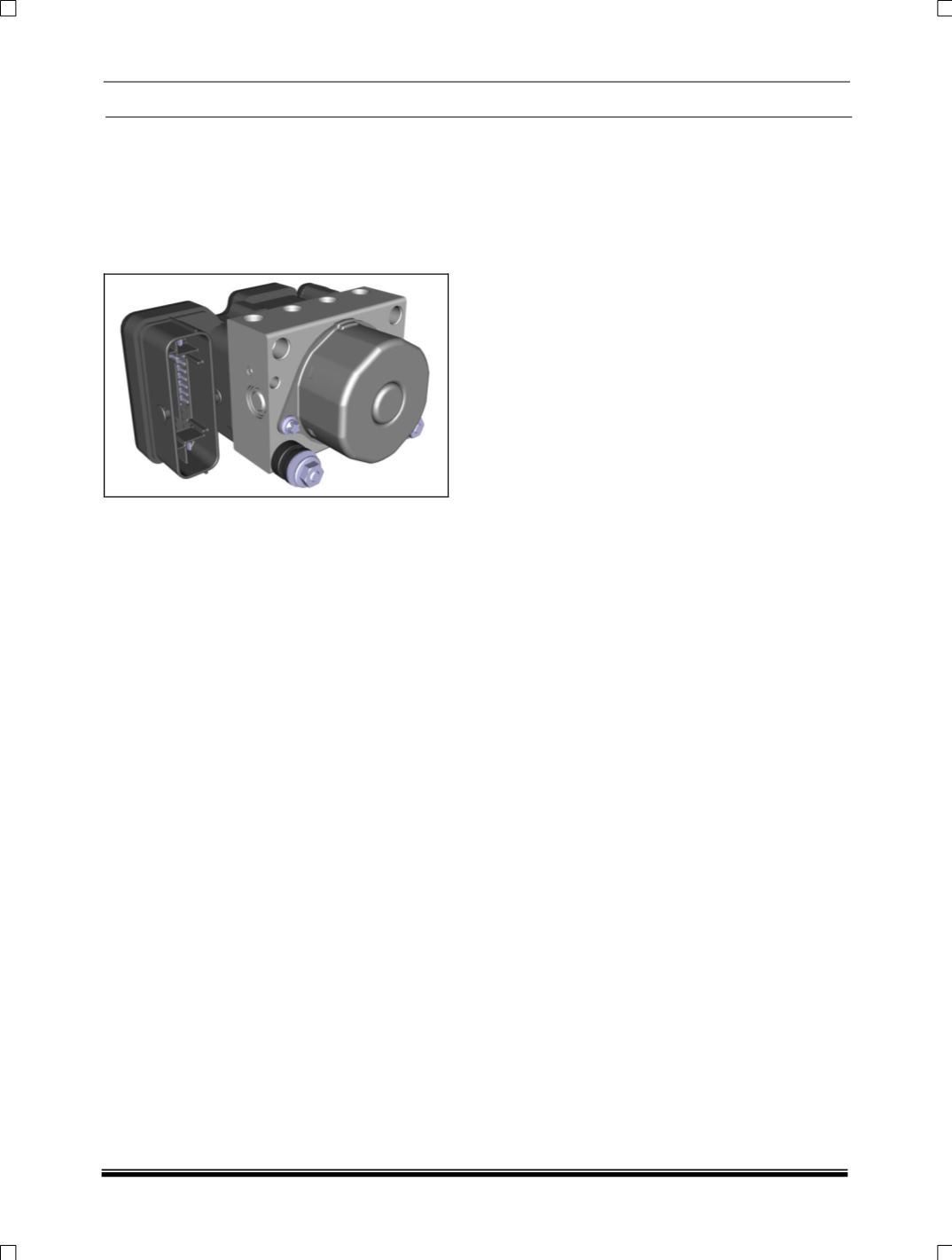
9.1. ABS 9 ELECTRONIC CONTROL UNIT /
HYDRAULIC CONTROL UNIT (ECU / HCU):
General
This is an Electro-hydraulic device for reducing,
holding & restoring pressure to one or more-wheel
brake, independent of the brake pedal effort
applied by the driver.
It consists of:
i. An Electronic Control Unit (ECU) and
ii. A Hydraulic Control Unit (HCU).
(i) ECU:
Solid-state electronic device containing computer
functions, sensor signal processing circuits, output
device drives for the various ABS valves &
components and Failure Detection Logic.
The ECU is integrated in a single package with the
Hydraulic Control Unit (HCU). It has 2 Micro
controllers, which utilize the same program for
independent data processing and monitoring
functions. One of the Micro controllers has an
EEPROM to retain memory data in case battery
supply is interrupted. The EEPROM is a non-
volatile data storage device employed to store
error codes, which can be read out for diagnosis.
When an error is, encountered ABS switches itself
off and triggers the ABS warning lamp. An
independent module controls the solenoid valve
relay and return pump motor.
ABS ECU senses the rotational speed of the
wheels and calculates the vehicle speed based on
the signal received from the wheel speed sensor.
During braking, deceleration will vary on pedal
pressure, the vehicle speed during braking, and
the road surface conditions. For example,
deceleration rate will be much higher on dry
asphalt compared to wet or icy surface.
ECU judges the slip condition between the wheel
and road surface by monitoring the change in
wheel’s rotational speed during braking. The ECU
controls the ABS actuator to deliver the optimum
hydraulic pressure to the brake cylinder to
precisely control the speed of the wheels,
maintaining the maximum brake force.
(ii) Hydraulic Control Unit (HCU)
General:
It consists of a Return Pumps, Solenoid Valves,
Accumulator, and Motor. It forms the link between
the TMC and the foundation brakes. It implements
the commands is- sued by the ECU by using
solenoid valves to control the pressure at the
foundation brakes.
There are four pairs (4-channel system) of Inlet
and Outlet valves and are located in the upper
section of the modulator. Solenoid valves are
responsible for modulating the pressure in the
brake cylinder during active ABS control.
The Return Pump element is installed in the
center of the modulator and is driven by an
electric Motor.
The pump transfers the brake fluid emerging from
the wheel brakes through the accumulator on its
way back to the TMC The pump actuation can be
felt on the foot pedal as pulsations.
Accumulator are Located in the lower section of
the hydraulic modulator. The accumulator absorbs
the surge in brake fluid that accompanies the
pressure reduction phase.