


 177 / 1006

1.2L REVOTRON ENGINE
166
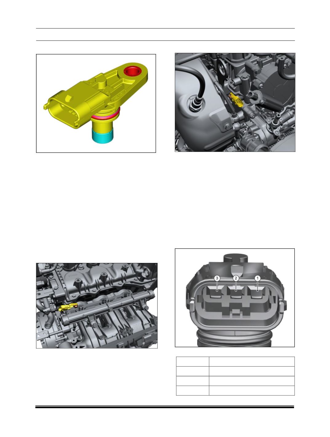
III. CAMSHAFT POSITION SENSOR
COMPONENT DETAILS
A typical Hall Effect Sensor has three wires or
terminals: one for ground, one for supply or
reference voltage and one for the output signal.
To produce an output signal, a Hall Effect Sensor
must be supplied with a reference voltage. When
a metal/wheel passes through the air gap
between the magnetic field (Magnet) and silicon
chip (CAM sensor), it blocks the magnetic field
and causes the chip’s output voltage to suddenly
drop to zero else the chip's output voltage is 4.7
Volts.
COMPONENT LOCATION
The cam phase sensor is mounted on cylinder
head.
1. Intake Camshaft Sensor
2. Exhaust Camshaft Sensor
PRELIMINARY CHECKS
1. Loose / Damaged connections between
sensor and EMS ECU.
2. Check for back out of pins at both sensor
connector and ECU connector.
3. Check for damage of pins at both sensor
connector and ECU connector.
4. Check the continuity from sensor connector
pins to the ECU pins.
5. Physical damage to Cam target wheel.
6. Improper air gap between sensor and cam
target wheel.
CONNECTOR DETAIL
PINOUT DETAILS
PIN
DESCRIPTION
1
Ground (-)
2
Output
3
Supply Voltage (+)
COMPONENT SPECIFICATION