


 1003 / 1006

SUPPLEMENTARY RESTRAINT SYSTEM (SRS)
18
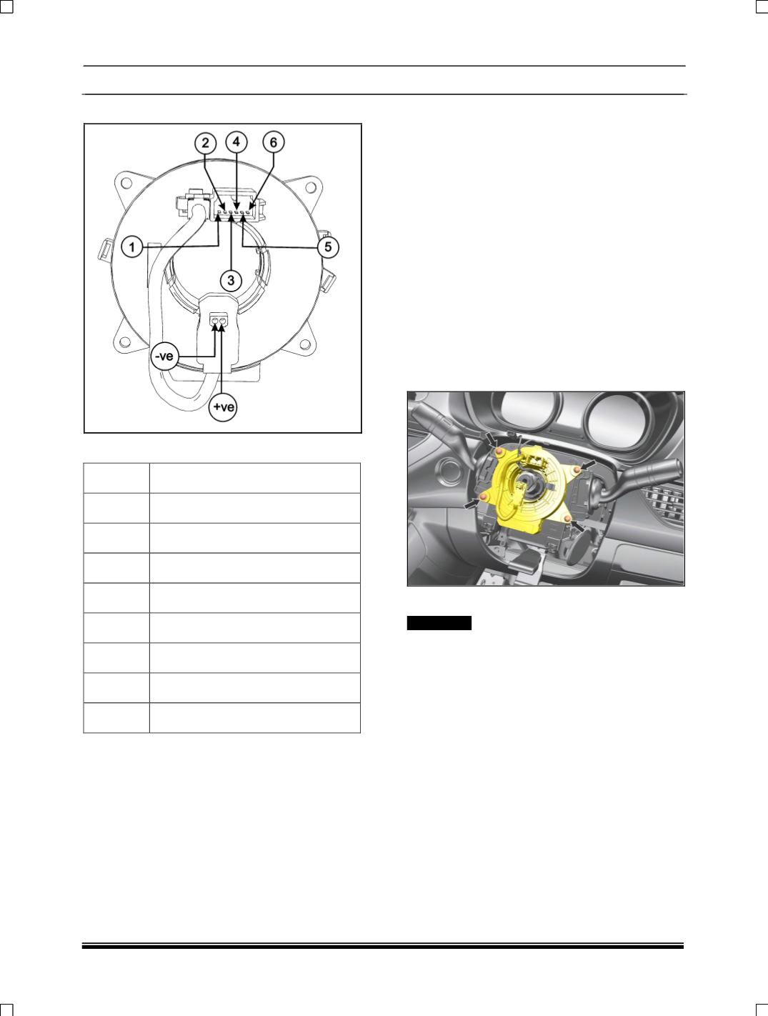
B. TOP SIDE CONNECTOR
PINOUT DETAILS
TRACK
FUNCTION
– VE
Air Bag
+ VE
Air Bag
1
Infotainment switch
2
Infotainment Ground
3
Cruise Switch
4
Cruise Ground
5
Horn Switch (+Ve)
6
Horn Switch (-Ve)
ON VEHICLE REPAIR
REMOVAL
1. Disconnect the battery and wait for 2 minutes.
2. Remove the DAB. (For procedures refer DAB
removal).
3. Remove the steering wheel (For procedures
refer steering wheel removal in steering
section).
4. Loosen three fixing screws of assembly
nacelle lower and assembly nacelle upper,
located in bottom side of assembly nacelle
lower.
5. Dismantle both nacelle from snap fitting and
take out the both assembly nacelle.
6. Remove four mounting screws of clock spring
and take out the clock spring.
FITMENT
! CAUTION
Care should be taken that before fitment of clock
spring, make sure that the steering wheel and the
vehicle is in straight ahead position.
For fitment follow the reverse procedure of
removal.
NOTE:
After fitment of clock spring on Combi switch align
the clock spring as follows: