


 222 / 516

DRIVESHAFT
9
10. ASSEMBLY
PROCEDURE
FOR
DRIVESHAFT:
1. Install the new small Boot retaining clamp on
the neck of the Boot. Do not crimp the small
Boot retaining clamp.
2. Slide the tripot Boot into the axle shaft,
passing over the Boot grooves of the axle
shaft towards the CV end of the axle.
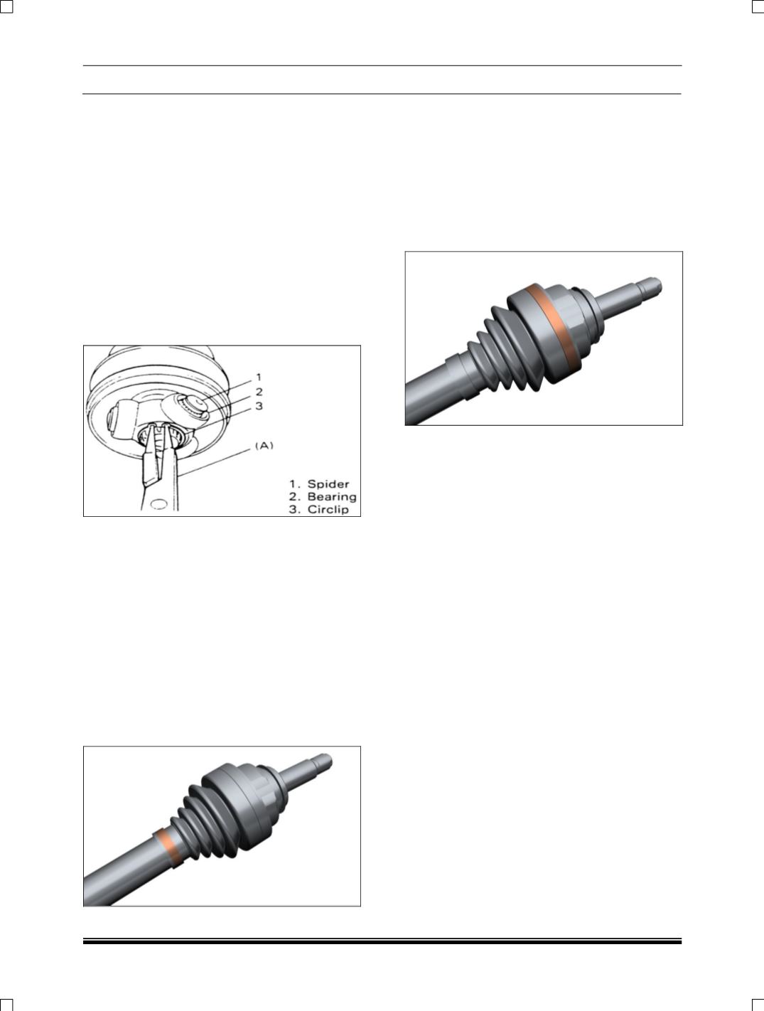
3. Place the tripot spider assembly on to the
drive axle shaft.
4. Assemble the spider assembly to the axle
shaft and tap gently if required. Insert the new
circlip ring using the plier
Important:
Ensure that the ring is fully seated
in the groove on the axle.
5. Transfer approximately half of the grease
from the service kit into the Boot and half
grease into the tripot housing. Slide the
housing over the spider assembly on the
shaft. Engage the tripot Boot with the tripot
outer.
Important:
The end of the tripot Boot must be
next to the Boot stop on the housing.
6. Slide the tripot Boot smaller end to the
corresponding groove on the axle shaft and
crimp the small Boot retaining clamp (new
one) using pincer crimping tool) and maintain
max 2.6 mm. ear gap as shown below.
(Spider Assembly at approximately middle of
the tripot bowl).
7. Slide the new large Boot retaining clamp over
the housing in the free condition of the boot
and housing Insert the swage tool part no:
2779 5890 2001 over the clamp.
8. Align the Boot bigger diameter on the housing
and position the big Boot retaining clamp in its
place and swage the large Boot-retaining
clamp using spanner Please tighten
alternatively between two bolts (i.e. don’t
tighten one bolt alone completely at a time).