


 741 / 745

ELECTRICAL
99
OR vehicle lock command is received, ESCL gets
locked.
(Wheel speed shall be less than 10 rpm and
Engine RPM shall not available).
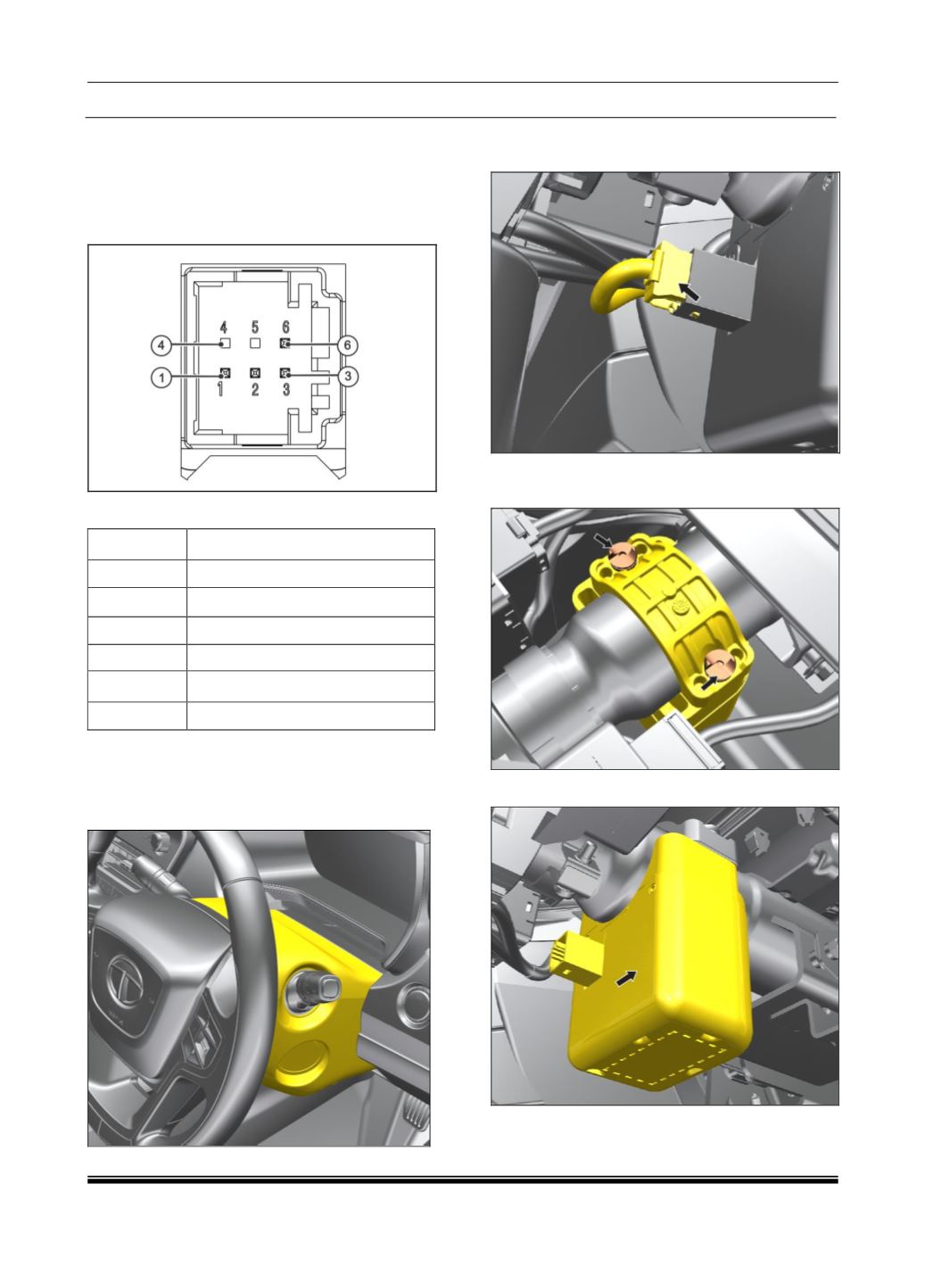
PINOUT DETAILS
CONNECTOR DETAILS
PIN
DESCRIPTION
1
Battery_Supply_+12V
2
CAN1-H
3
CAN1-L
4
(Reserve)
5
(Reserve)
6
GND_+12v
REMOVAL
1. Remove steering nacelle assembly.
(Refer
steering column removal for the procedure in
Steering Section)
.
2. Disconnect the electrical connection to the
ESCL.
3. Remove the ESCL mounting bracket’s dome
screw (2 qty.).
4. Take out the ESCL unit.
REFITMENT
Follow the removal process in reverse.