


 254 / 1119

1.5L REVOTORQ ENGINE
66
6. ENGINE SYSTEMS
A. AIR INTAKE SYSTEM
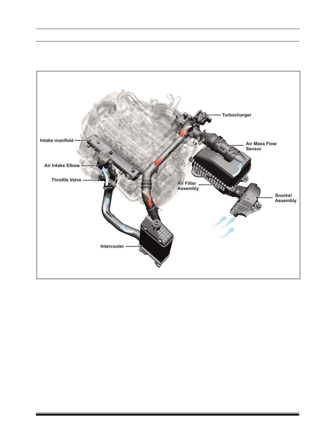
Air Intake System Schematic Layout
Description
Air is drawn into the combustion chamber through
the air intake system as shown in above schematic
layout. The air intake system should have the ability
to supply sufficient quantity of air to the engine.
The Air is driven to intake manifold primary due to
the suction created by the Engine. The Fresh air
from atmosphere is made to pass through an Air
Filter and into the WGT (Turbocharger). Here air is
compressed by WGT which is driven by Exhaust
gases. It then passes through the intercooler where
it made to dissipate the heat gained by compression
and passing through WGT which is located on the
exhaust manifold. From here it is drawn into the in-
take manifold and into the engine.
WGT limits exhaust gas inflow to less than its max-
imum capacity to prevent overload in advance.
Because this technology provides an engine with
high durability and better economic efficiency.
The Air intake System consists of the following
components.
1. Air Filter.
2. Intake Manifold
3. Intercooler.
4. Air Mass Flow Sensor
5. Snorkel Assembly
6. Throttle Valve
7. Air Temperature Sensor