


 1091 / 1119

SUPPLEMENTARY RESTRAINT SYSTEM (SRS)
17
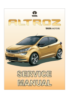
CONNECTOR
PINOUTS
PIN NO.
PIN DESCRIPTION
1
SIGNAL
2
GROUND
SUPPLY VOLTAGE LEVEL
Minimum
5.25 V
Nominal
6.20 V
Maximum
16.5 V
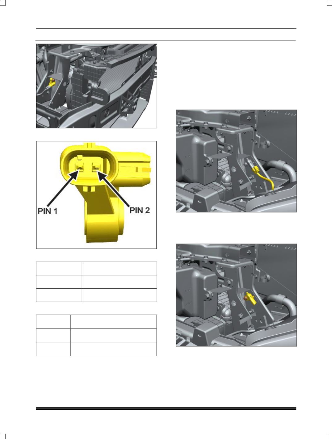
ON VEHICLE SERVICE
REMOVAL
1. Disconnect the battery connection.
2. Remove front bumper. (
For removal refer Body
section.
)
3. Disconnect the electrical connection from the
front impact sensor.
(LH side illustrated similar
procedure to be follow for RH side
).
4. Loosen and remove the mounting flange bolt
and take out the front impact sensor from the
vehicle.
(LH side illustrated similar procedure
to be follow for RH side
).
FITMENT
For fitment, follow reverse procedure of removal.