


 769 / 924

ELECTRICAL
151
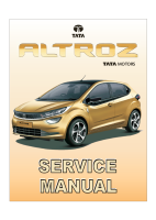
PINOUT DETAILS
CONNECTOR DETAILS
PIN
DESCRIPTION
1
Battery_Supply_+12V
2
CAN1-H
3
CAN1-L
4
(Reserve)
5
(Reserve)
6
GND_+12v
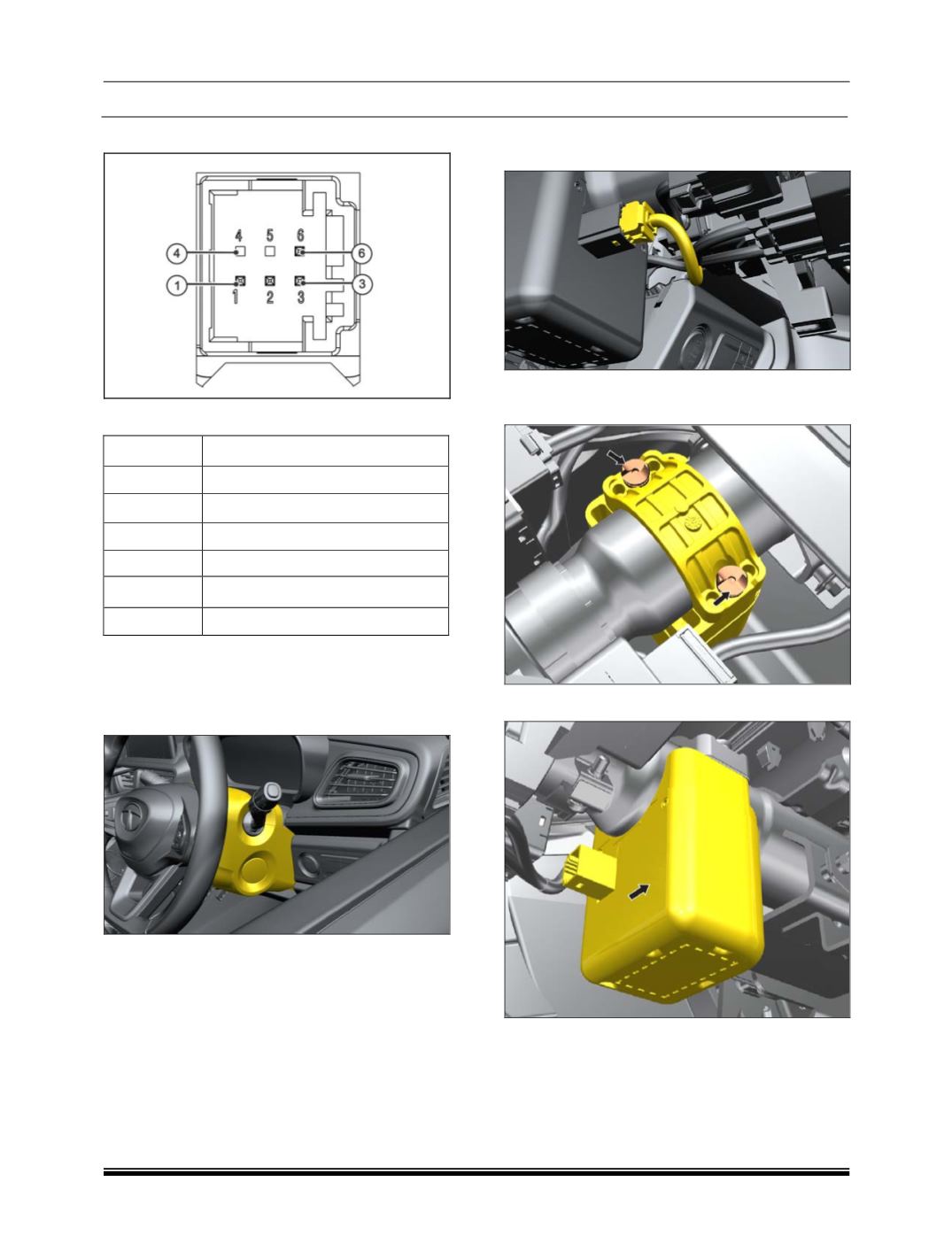
REMOVAL
1. Remove steering nacelle assembly.
(Refer
steering column removal for the procedure in
Steering Section)
.
2. Disconnect the electrical connection to the
ESCL.
3. Remove the ESCL mounting bracket’s dome
screw (2 qty.).
4. Take out the ESCL unit.
REFITMENT
Follow the removal process in reverse.