


 532 / 924

BRAKES
30
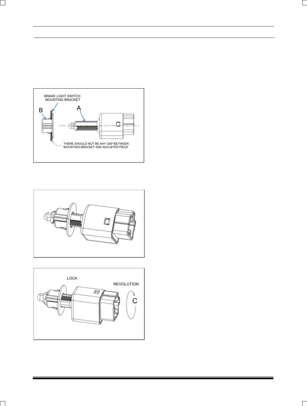
13. SNAP TYPE BRAKE LIGHT SWITCH
INSTALLATION PROCEDURE
1. Adjuster (B) to be snapped on Brake light
switch mounting bracket.
2. There should not be play in the adjuster after
fitment with mounting bracket.
3. Insert the switch (A) in adjuster (B) till the
switch plunger get completely Pressed
against brake pedal (at this point switch body
will rest on brake pedal)
4. Rotate the switch in direction ‘C’ till its lock.
5. After locking the switch will set back by
1±0.15mm.
INSPECTION OF BOOSTER OPERATION
NOTE:
Before inspection, make sure that there is no air
in the hydraulic system.
3. Check air tightness
a. Start and stop engine, after running for 1 to 2
minutes.
b. Depress brake pedal several times with the
same effort as used while normal braking
operation and observe pedal travel. If pedal
goes deep down for first time and its travel
decreases for the following depression, then
air tightness is observed.
c. If pedal travel doesn’t change then air
tightness is not obtained. Inspect vacuum lines
and sealing parts and replace defective parts.
d. Repeat the entire test after replacing defective
parts.
4. Check operation
a. With engine stopped, depress pedal for
several times with the same effort as used
while normal braking operation and make sure
that pedal travel doesn’t change.
b. Start engine and depress brake pedal. A small
increase in pedal travel indicated satisfactory
functioning of booster. But if there is no
change in pedal travel, it indicates a
malfunction.
5. Check air tightness under load
a. Start engine. Depress brake pedal. Stop
engine while holding the brake pedal in
depressed condition.
b. Hold the brake pedal in depressed condition
for 30 seconds. If pedal height doesn’t change
it indicates proper operating condition and if
pedal travel rises it indicates malfunctioning.