


 479 / 924

STEERING
13
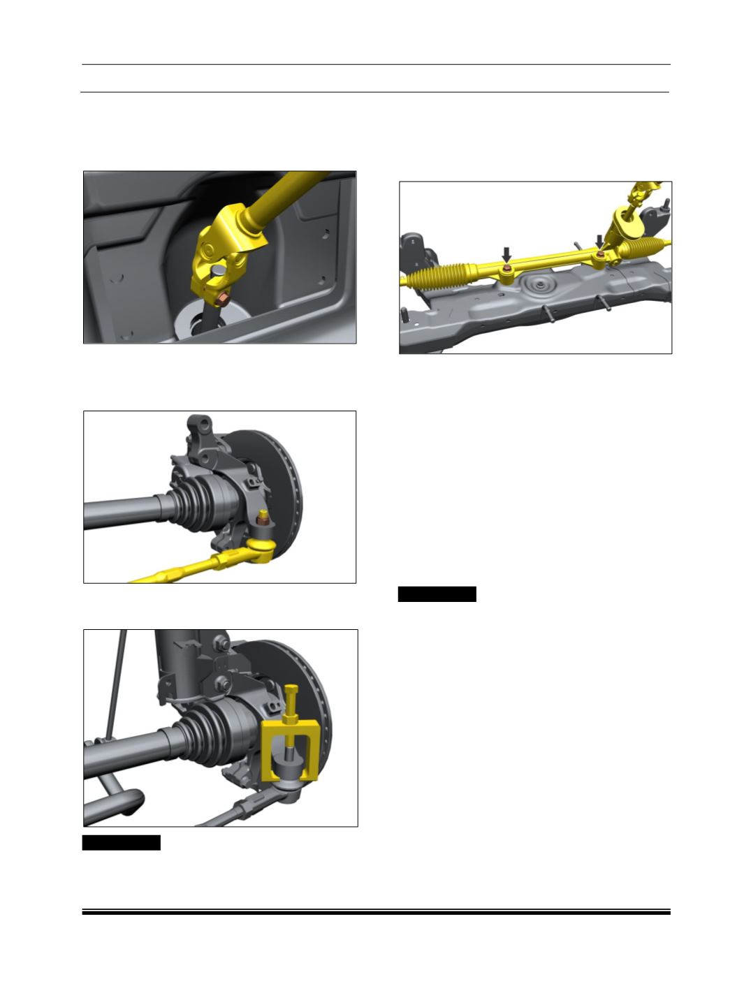
7.4. RACK & PINION ASSEMBLY REMOVAL
1. Remove lower universal joint bolt and make
steering rack free from the steering column
assembly.
2. Remove both front wheels (Refer wheel
removal procedure / Wheels and tyres group).
3. Remove tie rod ball joint nyloc nut.
4. Remove tie rod end by using tie rod ball joint
puller. (Part No. 2871 5890 4601).
!! WARNING
Steering arm should not be hammered for removal
of tie rod outer ball joints as this may lead to
damage of steering arm part.
5. Follow steps 3 and 4 to remove tie rod ball joint
from other side.
6. Remove two mounting bolts of steering rack
and pinion assembly from Steering gear
mounting panel.
7. Take out steering rack and pinion assembly
from either side of steering knuckle.
REFITMENT:
1. Keep the front wheels in straight ahead
position.
2. Follow the reverse procedure of removal.
NOTE:
Wheel alignment is necessary after installation
(Refer wheel alignment procedure).
There is a poka-yoke provided at steering
pinion to lower and upper universal joint (UJ)
mounting. The UJ can be fitted in one
direction only.
!! WARNING
Do not reuse the OBJ nyloc nut.
Do not reuse universal joint bolt.
INSPECTION:
1. Remove firewall seal from the steering rack and
pinion assembly and inspect the condition of
firewall
seal i.e. for any cut or damage. Replace
firewall seal if found damaged.
2. Inspect steering rack for any external damage.
Replace damaged or worn out parts.
3. Check condition of tie rod ball joint. If found
cracked or excessive play, replace ball joint.
4. Replace tie rod ball joint nylon nut.
5. Check free rotating torque of pinion shaft. If
found jammed, replace steering rack assembly.
Inspect rubber bellows for any rupture