


 205 / 924

CLUTCH_DIESEL
19
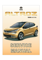
8. Remove the contactless clutch sensor.
FITMENT
For fitment, follow reverse procedure of removal.
STAY ROD ASSEMBLY PROCEDURE
Assemble the clutch assistance spring followed by
pivot pin on the stay rod.
Insert the stay rod assembly in the control
bracket, press the clutch pedal downwards and
apply sufficient pressure to compress the spring.
Keeping the spring compressed, insert the stay
rod assembly into the clutch pedal pin and press
the circlip to lock the stay rod assembly.
CAUTION:
The pin should be free of any rust or paint or dent
marks. If found the same need to be cleaned.
The pin needs to be properly lubricated with
Grease (Grease 3%MoS2, SS: 6820-320, TS:
25205PI) before mounting the stay rod on pedal
again.
The stay rod should have free rotational /
swiveling movement about pin axis during pedal
movement.
Before fitment of stay rod insure that pivot pin is
properly lubricated with grease (Grease 3%MoS2,
SS: 6820-320, TS: 25205PI).
C. CONTROL
BRACKET
ASSEMBLY
REMOVAL
1. Disconnect battery connection.
2. Pry out the lower cover of steering column.
3. Pry out the nacelle lower of steering column.
4. Disconnect the electrical connector from the
clutch switch
.
5. Remove the Steering column assembly from
intermediate shaft end.
(For procedure refer
Steering section).
6. Remove the brake booster assembly
(Refer
On
Vehicle
procedure of booster assembly
removal in brake section)
7. Disconnect the electrical connecter of brake
switches and remove the brake switch
mounting bracket by removing its nuts.
(Refer Clutch pedal assembly removal from
this section.
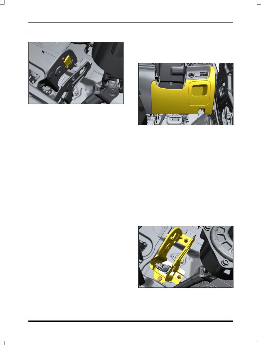
8. Remove all mountings on clutch bracket
assembly with clutch pedal stopper & take
out Bracket as shown below.