


 397 / 948

Anti-lock Braking System(ABS)
5
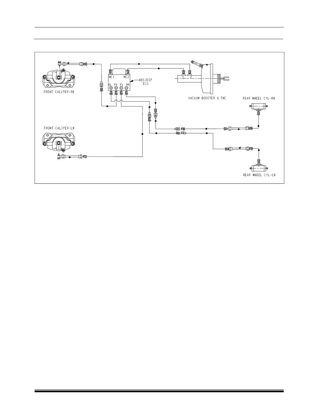
D. SCHEMATIC OF HYDRAULIC CIRCUIT :
General:
The Anti lock braking system consists of a
Hydraulic modulator with integrated Electronic
control unit, four wheel speed sensors (one
located at each wheel) and 2 warning lamps in the
instrument cluster (1(yellow) for ABS and 1(Red)
for EBD). The brake pipes are connected to the
brakes through the ABS ECU / HCU. They make
two independent circuits which are vertically split.
The primary circuit connects the Front Left and
the Front Right brake while the secondary
connects Rear Right and Rear Left brake through
connectors. Internal to the Hydraulic modulator
each brake has a pair of solenoid valves, one inlet
and one outlet; these are activated by the ECU to
control the brake pressure of individual wheels.